 Ask an Engineer
Linear actuators for gantry and multi-axis systems
By Andrew Zaske on September 10, 2020
 Gantry and multi-axis systems are used throughout manufacturing to lift, position and move loads. Simply put, gantries are a frame with coordinated moving components. They can be 2-dimensional with a simple XY axis, or 3-dimensional with XYZ axis, and carry loads from a few pounds to a few thousand, slow or fast, once a day or many times a day. They are used in pick-and-place applications and a variety of other automated processes.
Off-the-shelf gantry systems have their place for smaller footprint applications. But for larger weight, longer distances and higher force ranges you will need a flexible, robust high duty cycle multi-axis actuator solution. This customized solution creates infinite combinations that can be created to maximize flexibility, speed, efficiency and throughput.
Gantries are multi-component systems:
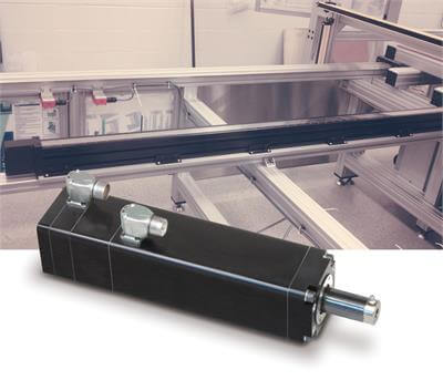
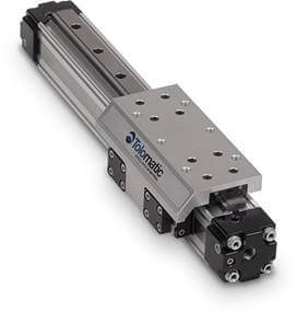
- Linear actuators drive the motion of the gantry along each axis. The X and Y axis actuators are usually rodless actuators (belt-driven or screw-driven), which move and carry loads throughout the footprint of the system. Rod-style actuators are often used for the Z axis, or the vertical, up-and-down motion.
- Transition plates create the link between actuators in a common plane of motion or in the transition from one plane to another. Multiple actuators are connected to each other, and there are many ways to do that, depending on the needs and complexity of the system.
- Auxiliary rails provide extra support to ensure the system can manage the load and guide the load.
- Cable management includes harnesses and cables, all of which are configured to match the electric or pneumatic power source and the motion profile.
- Jack shafts allow you to drive the system with a single motor and drive, as well as keep the actuators synchronized with each other. When the load is large or needs to move across a wide distance, a single actuator and rail won’t be sufficient. A single motor will drive a master actuator, which is connected to a similar actuator through a jack shaft. The jack shaft helps prevent wobble and vibration.
Gantry systems may include multiple components, but putting a gantry system together is not as complicated as it may seem and usually involves a few straightforward steps. Tolomatic, the local Tolomatic distributor near you, and its gantry partner, Solve NYC, will guide you through the process.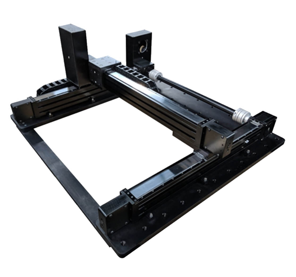
- Concept—Start with a napkin sketch or CAD layout concept, establish requirements for load and speed, and set a budget
- Identify key design considerations
- Movement (speeds, cycle time, accuracy, repeatability, dwells)
- Space (working envelope, stroke length, environmental concerns)
- Load (weights, load dimensions, forces, center of gravity)
- Sizing and selection—Based on the information provided, your motion control partners will determine the components that best match your requirements
- Interesting to note that actuator sizing is done backwards for gantry systems and starts with the Z axis. Moment load is then accounted for on the Y axis, and then the X axis.
- Final design—Based on the parameters, you will receive a CAD layout
- Final assembly—Upon approval, the gantry will be factory-assembled, integrated and field-tested.
Design for an XYZ gantry
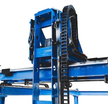
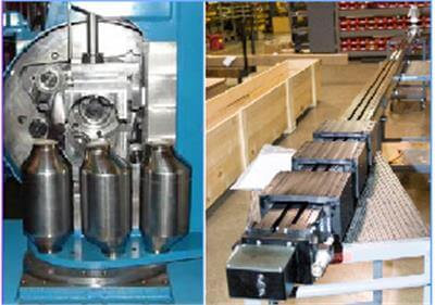
 This design for heavy ultrasonic welding requires a gantry system with long strokes (12-foot in/out feed tables); 4 x 6 foot working envelope; and 8-inch Z-axis ultrasonic tooling plate. The gantry is used to apply ultrasonic welds to large medical waste bags.
The ultrasonic welding process in this application was utilizing pneumatic actuators, which required manual adjustment in each new setup. Lack of fast and repeatable positioning control resulted in welding and dimensional inaccuracies, delays that slowed production time and created high scrap rates. The solution was to design an efficient electric motion control gantry that would provide consistent performance carrying the heavy ultrasonic tooling heads, in and out over long distances, on the feed tables.
A B3W linear belt-drive actuator was selected for the X- and Y-axis for its long stroke lengths and high load carrying capabilities for both the in-feed and out-feed table. Since accuracy and repeatability were primary concerns, servo motors with absolute encoders were selected for all 5 axes. An IMA33 linear servo actuator was selected for the Z-axis for its integrated servo motor design providing force feedback functionality from the motor/drive system to ensure speed and positioning consistency throughout the welding process.
The electric-driven gantry provides quick, accurate, repeatable ultrasonic welds and eliminates inaccuracies from manual adjustment as well as higher costs related to compressed air. The gantry also reduced product scrap and increased machine cycle time and product throughout.
Design for an XY gantry
This design for palletizing and slip-sheeting requires a gantry system with 72-inch horizontal and 62-inch vertical stroke and a 30-second complete cycle. The horizontal actuator carries the load (632 pounds) of the vertical actuator. The gantry is used to place slip sheets on pallets.
A manufacturer of palletizers for bagged, bundled and baled products was looking for an efficient way to place a slip sheet on top of pallets to ready them for loading (or palletizing). The X-Y gantry process needed to be fast, repeatable and stable to allow slip sheets to be dropped in multiple positions on the pallets.
A MXP-P profiled rail pneumatic cylinder achieves the smooth linear motion required. One MXB-P actuator mounted on the X-axis moves to position the Y-axis MXB-P actuator over the paper sheets. The X-Y configuration moves down, picks up the sheet, moves up and over into a new position on a pallet. Sensors were implemented along the horizontal stroke of the X axis MXB-P actuator to signal position.
The gantry helps increase machine efficiency and uniformly places slip sheets on all pallets.
For more information, see our brochure on gantry and multi-axis systems.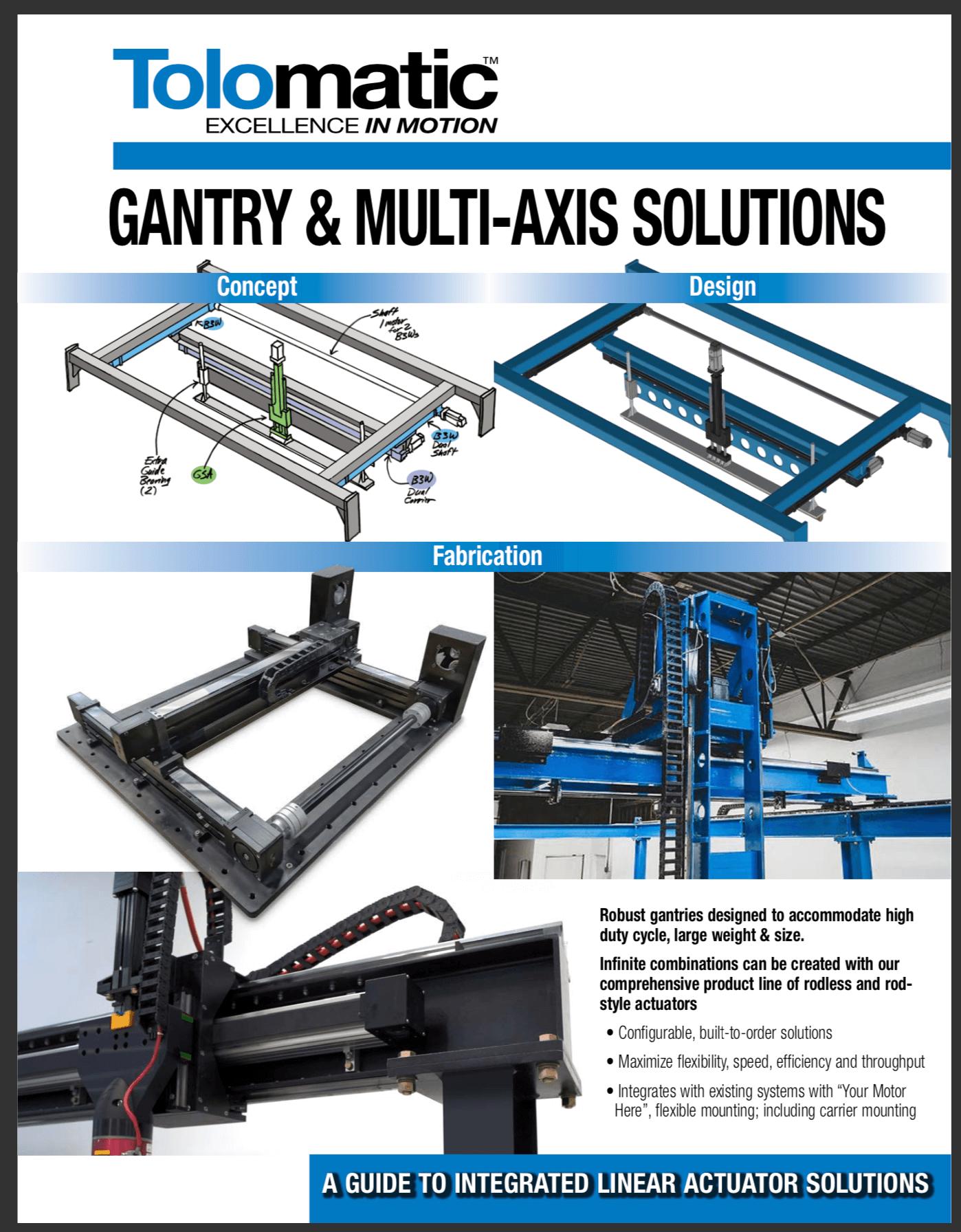
Find out which gantry system is best for your application. Contact a Tolomatic engineer. Or check out our sizing software.