 Ask an Engineer
How to convert high-force linear actuators from hydraulic to electric
By Ryan Klemetson on February 5, 2019
 Things are changing in industrial automation. Many linear motion applications are getting more sophisticated with increased demand for control of process variables like velocity, thrust, acceleration/deceleration and more.
It’s common for new applications that require high thrust from a linear actuator to use electric motion systems. Moreover, machine designers are converting existing hydraulic motion systems to electric. The benefits of this conversion are many. (Read about hydraulic versus electric linear motion here.) The process of replacing a hydraulic system with an electric actuator involves considering the actual force output of the cylinder, the duty cycle and the entire motion profile. Our recommended best practices for conversion are in our new Guide, How to convert hydraulic cylinders to an electric actuator alternative. Download your copy here.
Our previous blogpost, High-force linear actuators: how to convert from hydraulic to electric, Part 1 of 2 provided tips on determining the force an application requires. This post will look at defining the motion profile.
Understanding the entire motion profile
Converting a hydraulic high-force linear actuator to electric goes beyond determining force requirements. You need a fundamental  understanding of the process to ensure that your final electric linear motion system is appropriately sized.
Start by defining the entire extend and retract cycle, including distances, speeds (extend/retract time), duration of dwells, and even acceleration/deceleration times. Variables like speed and force may not be consistent throughout the entire motion profile. Often there are periods during which very high speeds or an increase in force is required. These portions of the motion profile need to be accounted for in addition to the remainder of the cycle.
Linear motion control components (actuators, servo motors, power screws) have peak and continuous ratings for speed and force and can only operate in the peak area of their ratings for brief periods of time throughout the process. During one complete motion cycle (extend, dwell, retract, dwell), the average speed and force must fall within the continuous operating region of the components’ ratings. Exceeding the continuous operating region of any of these components can diminish service life.
Hydraulic high-force linear actuator applications can have varying thrust requirements throughout their cycles. It is quite common, though, to have a consistent speed in one or both directions. This can make determining your cycle times easy. We recommend taking a video or using a stop watch to determine the duration of every move and dwell in the motion cycle.
Improving the process
If you’re putting in the effort to convert a hydraulic system to electric, look at the process itself for improvements. For example, a hydraulic application may cycle full stroke (extend and retract) during a repetitive pressing application. An electric actuator may need to extend and retract only  1” or 25mm to perform the same process, only performing a full retract for changing tooling or servicing. This can mean significant time savings.
Processes also may benefit from improvements through utilizing the ability of a servo-controlled electric linear motion system to fully control position, velocity, acceleration/deceleration and force. These improvements can lead to increased part quality and reduced product scrap or rejects.
Selecting technologies
Once you’ve figured out your application’s forces and speeds, you can select the actuator power screw, servo motor and drive to complete the electric linear motion system. When making your selection, also consider the application’s requirements for size, weight, service life, IP rating and other factors.
- Power screw There are several power transmission mechanisms commonly used in electric actuators. This includes three types of screw technologies: acme, ball and roller. Roller screws are often favored in high-force applications since their combination of rolling and sliding elements and greater surface area can handle the stresses of high torques. Also, roller screws are very power dense and provide the most compact actuator packaging to replace hydraulic cylinders.
- Servo motor, drive, gearbox Selecting the best servo motor for an application can mean balancing the needs of torque and speed. Large frame size servo motors will typically have very high torque at low speeds and limitations of between 1500-3000 RPM while smaller servo motors have lower torque but a typical range of up to 6000 RPM.
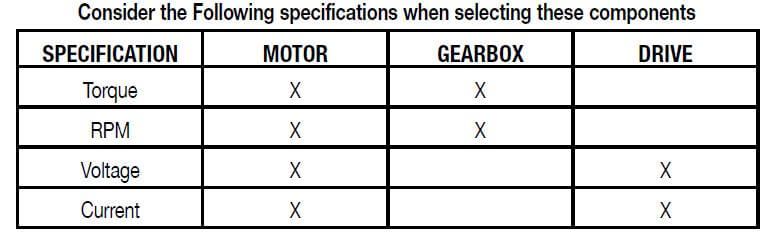
By the time you select the motor, you should understand the power requirements for the servo drive. Most servo drive manufacturers offer a wide range of sizes and power outputs, so you probably will spend most of your efforts making sure all the communication and functionality requirements are met.
Ask an expert
It’s not difficult to convert from hydraulic linear motion to electric, and the benefits are clear. If you want assistance with the process, work with a linear motion specialist to get it all just right.
Resources
For our recommended best practices for conversion, download our new Guide, How to convert hydraulic cylinders to an electric actuator alternative.