 Ask an Engineer
Demystifying electronic camming
By Tolomatic on July 14, 2020
Mechanical camming is ubiquitous in 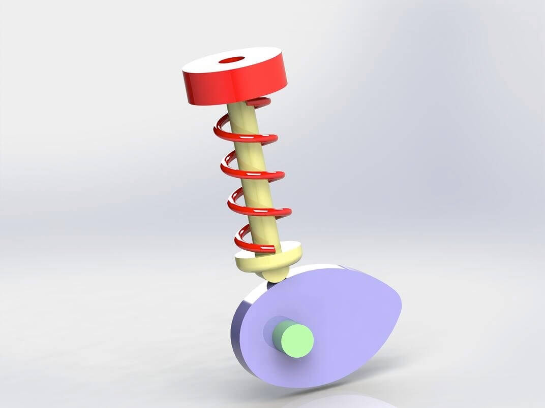 factory automation system systems. But how do you switch from a mechanical camming system to an electronic one? And why would you? In this blog, we’ll review mechanical camming, look at dwell times and cam profiles, and then examine how mechanical camming translates to electronic camming and what advantages it provides.
Mechanical cam systems
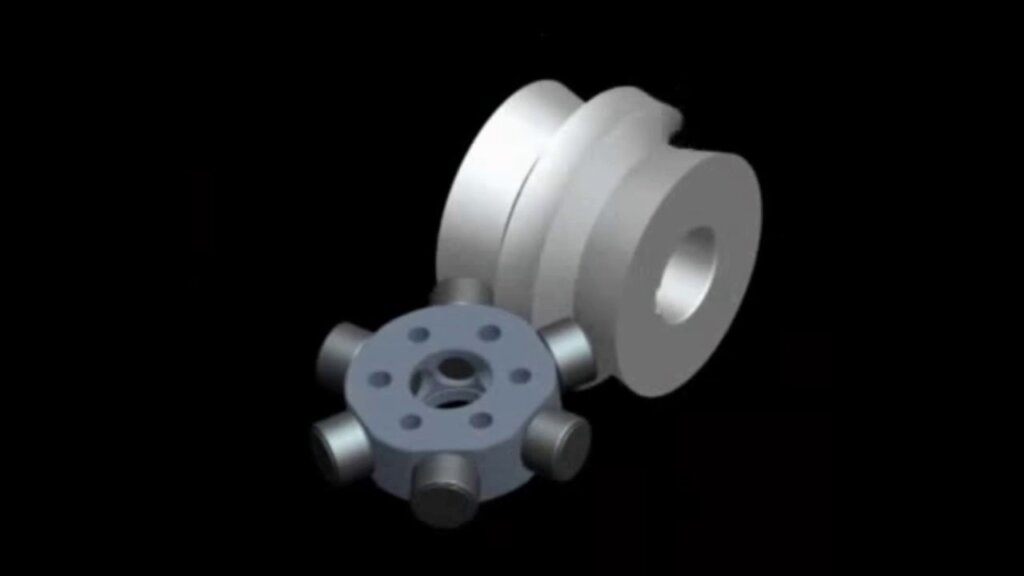
The purpose of all mechanical cam systems is to convert continuous rotary motion into intermittent linear or rotary motion.
One of the most common examples of mechanical camming is the camshaft of an automobile, which takes the rotary motion of the engine and converts it into the reciprocating motion necessary to operate the intake and exhaust valves of the cylinders. 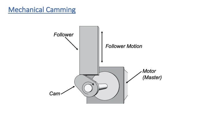
Mechanical cam systems consist of a master input, which is typically driven by a constant-speed motor; a cam; and a follower. The master provides continuous motion. The follower creates intermittent motion.
That’s one of the beauties of mechanical camming or camming in general: The motion and dwell times all scale depending on the line speed of your constant-speed input.
The positions and dwell times of camming mechanisms are plotted on graphs called cam profiles. A cam profile depicts the master axis position along the horizontal axis, and the follower position along the vertical axis.
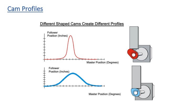
The shape of the mechanical cam affects the cam profile. For example, a profile with fast acceleration and long dwell time has a steeper profile. A shallower profile has lower acceleration and longer dwell time.
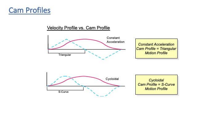
There are two common types of cam profiles. A constant acceleration cam profile (acceleration is constant as you go from positivity velocity to negative velocity) shows the cam profile as an s-curve and the velocity profile as linear. A cycloidal cam profile produces an s-curve velocity profile. In other words, a constant acceleration cam provides a linear velocity profile and a cycloidal cam provides a s-curve velocity profile.
Electronic camming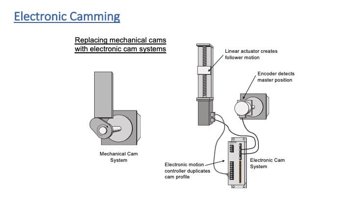
This is all cool stuff about mechanical camming, but what happens when we get into electronic camming?
To create an electronic cam system, you need to reproduce what the mechanical cam system does. You need three things:
- An electric actuator that provides the follower motion;
- A motion controller that can provide the variable gearing that is accomplished with a cam system;
- A master encoder, or some way of detecting the speed and position of your master axis.
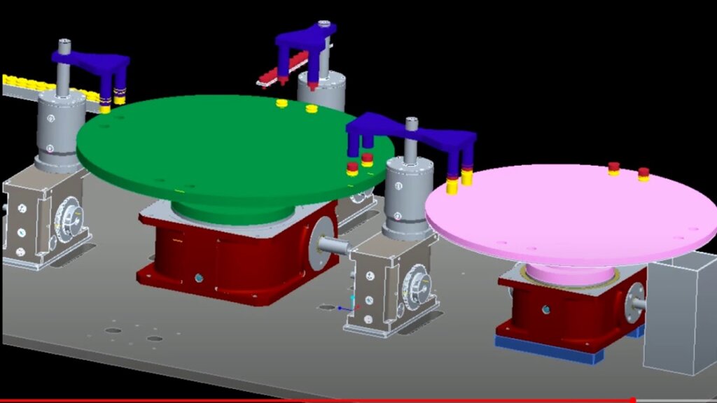
Here’s how that works on a case-packer machine:

When you implement electronic camming, it really simplifies the programming for your machine. Instead of having to have different velocity profiles for each different speed of the machine, you just cam every axis to one master axis, and then as the speed of that master axis changes, all of your cams slow down or speed up in perfect synchronism with the master axis. It makes machine motion-control profiling much easier. Really cool!
Application example: Electronic cams increase changeover flexibility on bagging/filling machine
A leading packaging-machine builder had to accommodate bags of different sizes for filling and sealing. Their customers had begun to switch from standard sized, high-quality bags to lower-cost bags with inconsistent dimension. This led to problems with improper filling and sealing. The solution needed to allow for quick adjustments to accommodate varying bag sizes accurately and consistently.
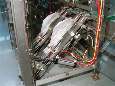
The camming system: Four modified-standard ball-screw linear actuators (B3S10) precisely position the incoming bags before they are inserted into the filling/sealing line. Two actuators adjust for vertical position and two horizontal actuators center the bags in their trays. A set of the actuators are coupled together, incorporating right hand/left hand screws, to get 2 axes of motion from one motor.
Using electric linear actuators and electronic camming boosts packaging productivity and accuracy, and provides flexibility for many different sizes of bags.
The main benefit of electronic camming is that you don’t need to change out the mechanical cams in your machine when you change different product sizes because the cam profiles are stored digitally in your motion controller.
Another advantage of electronic camming is that all of the different cam profiles for different product sizes or different machine variations can all be changed as you select different I/O or network commands or motion program conditions.
Bottom line: Machine flexibility is dramatically increased when you switch from mechanical to electronic cams.
Want to know more about how you can benefit from electronic camming? Contact a Tolomatic engineer and start a conversation.
Need to size an actuator for electronic camming? Check out our sizing software
For further reading:
- Motion Control Tips: What is electronic camming?