 Ask an Engineer
Gantry and multi-axis system: Build it your way
By Andrew Zaske on August 3, 2021
Follow a straight-forward four-step method
With gantry systems, there are lots of opportunities to make design decisions, to make mistakes—and lots of opportunities to do things in a very creative way. The easiest choice might be an off-the-shelf system. But if you have weight, force or size challenges that don’t fit within the off-the-shelf parameters, a better bet would be a fully integrated customized approach. It’s easier than you might think. It starts with a back-of-the-napkin concept drawing from you.
For starters, take a look at our info page that summarizes the entire process.
There are endless ways to create a gantry system.
- You can install one actuator with a second actuator attached to its carriage. That’s a standard XY configuration.
- You can install two axes in a parallel fashion to create a base of support for a second or third axis.
- You can mount the actuator to the carriage and move the actuator back and forth, across and back.
- More complicated systems designed in an X, Y, Z configuration add the up and down motion to create three different axes of movement.
- And many, many more…
Whatever the configuration, gantry systems with the correctly sized industrial actuators are robust, designed to accommodate high duty cycles, large weight and size. To be successful, it takes the right combination of flexibility, speed, efficiency and throughput.
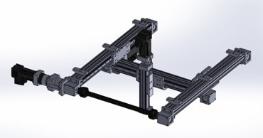
A gantry system includes multiple components: actuators, transition plates, base plates, cable management, end adapters, etc. Actuators that are used in the gantry system can include: rodless belt-drive, rodless screw drive, and rod-style actuators. Rodless belt-drive actuators can be designed to have stroke lengths of more than 30 feet (10 meters). Multiple carriers on a single-actuator axis can increase the load-carrying capacity and provide higher bending moment control capability. Jack shafts allow you to use a single motor/drive and also keep actuators synchronized so that two carriages move together. ![]() Other parameters include cable management, mounting configurations, framing, and end-of-arm tooling.
Other parameters include cable management, mounting configurations, framing, and end-of-arm tooling.
The good news is that you don’t have to figure all this out by yourself. Tolomatic has decades of experience building strong and configurable motion profiles, and partners with many distributors and integrators like Solve Industrial Design NYC to create the full system. Putting a gantry system together takes planning and engineering. There are four distinct phases.
The four-step process to building a gantry
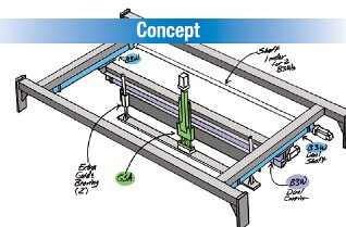
1. Concept phase: What does your gantry system need to do? Start with a simple drawing on a napkin, a Powerpoint sketch or a rough CAD layout. How fast does it need to be, what weight does it carry, how often does it move? What is your budget?
2. Design phase. From what we learned in the concept phrase, we’ll design a more sophisticated layout that includes the required components to meet the specified parameters. We look at movement (speeds, cycle time, accuracy, repeatability, dwells); space (working envelope, stroke length, environmental concerns); and load (weights, load dimensions, forces, center of gravity).
With this information, we recommend the type of gantry system and assemble the components in 3D drawings. In addition to actuators, the detailed design can include cable track and tray, transition plates, base plates, jack shaft and couplers, framing, and end-of-arm tooling.
3. Design refinement. The design is presented to the customer engineers and then we coordinate discussions of strengths and weaknesses of the design. Based on these discussions and marked-up drawings, the final design is modified based on your input.
4. Fabrication and integration. Once approved, the system is put on order. Any final engineering work is completed on the actuators and components. The various pieces are built, assembled and tested.
Following these four steps ensures a reliable system built to meet the application requirements. Take a look at these examples:
Pick-and-place gantry
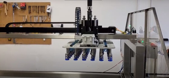
Here’s an example of a two-axis, pick-and-place gantry system that was built quickly and incorporated into an existing machine to operate fast. The gantry picks up cinnamon rolls off of one conveyor belt and moves them to a parallel conveyor belt. A B3W linear belt-drive actuator runs across the span of the two conveyors and a GSA linear slide actuator moves the load up and down. End-of- tooling grabs the cinnamon roll trays, weighing 250 lbs., and moves them from one conveyor to the other in less than two seconds. This high duty cycle system was built in less than four weeks.
Plating dip tanks, ultrasonic cleaning
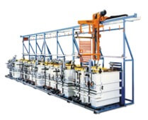
A rack-and-pinion system had been the design standard for many years to move parts into and out of dip tanks. However, the installation of the rack-and-pinion system required extra time, labor and carefully machines parts for final assembly in this plating system. The hold-up was the top rails, which had to be perfectly flat and smooth for mounting the rack and pinion system. Replacing this design with a rodless actuator gantry system changed all of that. A linear actuator-based gantry gives you precise movement, but avoids the installation headaches of alignment of a rack and pinion. Stroke-configurable B3 actuators provide the 22-foot X movement along the top, left to right. Another B3 provides the 8-foot up-and-down Y axis in and out of each dip tank. The electric motion program controls acceleration, deceleration and velocity through the every move.
Learn more about how creating a gantry system. Download our brochure.
Contact an engineer to discuss your application and start the design process.