10 tips for sizing pneumatic rodless linear actuators
By Gary Rosengren on February 10, 2015
 Pneumatic linear actuators are used throughout manufacturing to position loads reliably. When your application calls for a pneumatic rodless linear actuator (cylinder), use these tips from to ensure you size your linear actuator correctly.
Pneumatic rodless cylinder sizing
#1: Estimate the available air pressure accurately
Overestimating available air pressure can cause a loss in actuator performance or even a complete malfunction. The best solution is to check your air pressure with a gauge to get an accurate reading and then build in safe engineering practices. We recommend you factor in a 10% pressure loss from the gauge air pressure.
#2: Determine the actuator's working stroke and overall length
There is a portion of the actuator stroke that cannot be used due to the interference of internal components and the room needed to physically come to the end-of-stroke. This is normally referred to as the actuator’s "dead length." This dead length is determined by the manufacturer and should be indicated on the dimensional information.
To properly determine the actuator’s overall length (OAL), you must know the distance of travel (working stroke) and add this to the given dead length at each end of the actuator.
#3: Size the rodless cylinder accurately
When it comes to cylinder sizing, bigger is not necessarily better. It can cost more in both money and air consumption. On the other hand, under-sizing a cylinder may save a few dollars but will not provide optimal performance. The best performance is achieved when the actuator is sized based on the application’s load, force and bending moment (with a safety margin built in). Selecting the wrong cylinder can result in poor performance, reduced life, component wear and/or cylinder failure.
#4: Consider the effects of resulting moments (torques)
The size and position of the load on the cylinder's carrier determine the resulting bending moments or torques applied to the cylinder. Even if a load is located on and directly over the center of the load carrying device, it will still be subject to bending moments upon acceleration. It is important to determine if the cylinder is capable of handling the resulting moments on all axes of motion.
Published bending moments are usually a maximum and assume only one type of moment is being applied. In certain applications, compound moments can occur. Each needs to be evaluated and calculated per the manufacturer's equation to determine if the cylinder is capable of handling the combined moment force.
#5: Factor in the effects of dynamic moment loading
Many rodless cylinder applications support the load during acceleration and deceleration at each end of the stroke. When there are side or overhung loads the dynamic moments must be calculated.
Shock absorbers, mounted on the cylinder or directly on the machine framework, may be used to compensate for the inertial effects of dynamic loading. This stopping device should be placed near the center of gravity of the moving load.
#6: Understand the difference between average and impact velocity
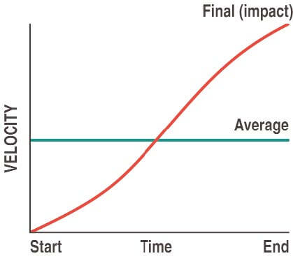
 Velocity calculations for all rodless cylinders need to differentiate between average velocity and impact velocity. For example, stroking a 24-inch actuator in one second yields an average velocity of 24 inches per second. A reasonable guideline for determining the final (impact) velocity is two times the average velocity. (2 x 24 in/sec = 48 in/sec impact velocity).
#7: Determine the cushion or shock absorber capacity
Most rodless actuators are equipped with internal devices to help cushion the load at end of stroke. It is important to know the impact velocity in order to determine the cylinder’s cushioning capacities. If the impact velocity cannot be accurately determined, consider using limit switches with valve deceleration circuits or shock absorbers.
#8: Factor in the effects of motion lag due to breakaway, acceleration, and friction
It is important to understand how other forces and losses affect the total force required to produce the desired motion.
Total force calculation:
Ft (total force) = Fa (acceleration force) + Ffr (friction) + Fbk (breakaway force)
#9: Vertical vs. horizontal applications
When a cylinder is mounted vertically in an application, there are additional force, load, and air considerations to address. A cylinder mounted vertically needs to overcome the force of gravity first before it can accelerate a load upward. In vertical applications, it is best to size a cylinder capable of twice the required horizontal force.
If the actuator is required to hold a load vertically for any length of time, the amount of air leakage in the system can affect how well that position can be maintained. Some type of holding device (such as a brake) or external guidance system may be required to safely control the load.
#10: Take into account the effects of the environment
Extremely hot or cold temperatures, external abrasives, dirty or wet conditions, caustic fluids, and air quality are just a few of the environmental conditions that can affect cylinder life.
Most manufacturers specify a cylinder’s performance based on normal operating conditions. If the cylinder will be in adverse environmental situations, discuss this with the manufacturer to determine if the cylinder is capable of delivering the expected performance.
In summary
Determining the right pneumatic rodless linear actuator can be a complex process because there are many different models, styles, and manufacturers to consider. Consulting with an experienced manufacturer improves the selection process. The result: long-life and trouble-free cylinder performance.
Download our white paper on sizing and selecting pneumatic rodless linear actuators for more on these tips.
