 Ask an Engineer
How to Convert Hydraulic Cylinders to an Electric Actuator Alternative
Introduction
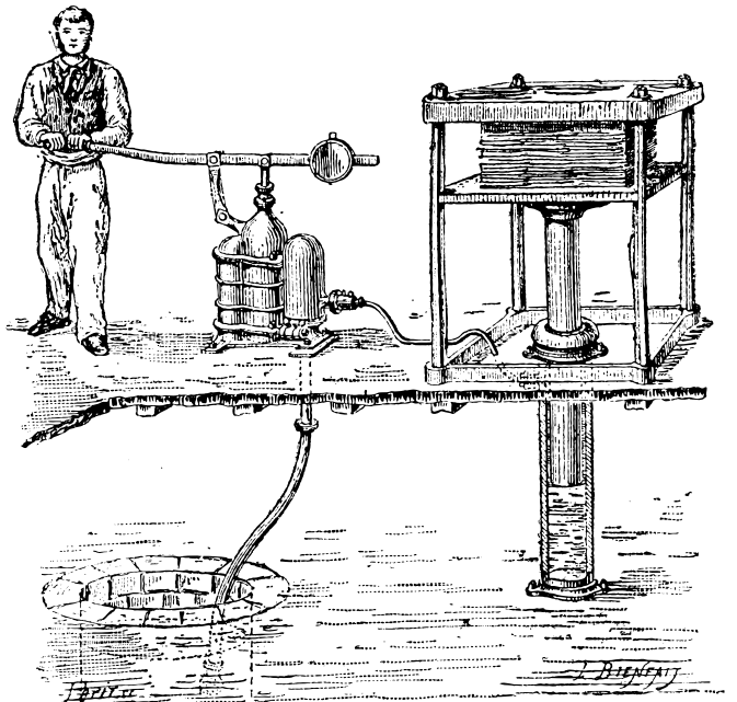
Hydraulics have been used to automate processes for centuries. From turning wheels on mills to providing basic machine power to modern day oil-based systems with complex cylinder, valve, and logic arrangements for very sophisticated automation. As technology advances, there are now many applications that benefit from better control, flexibility, efficiency and other factors that come with electromechanical systems. For a technology and feature comparison, read our white paper on Electric rod actuators vs. hydraulic cylinders: A comparison of the pros and cons of each technology.
Hydraulics will continue to have some benefits over other available technologies due to their high power density, relatively cost-effective components, and simplicity of deployment for simple point-to-point or mid-point positioning. As application requirements become more demanding, hydraulic systems must now use linear transducers and servo hydraulic systems which increase cost and complexity. It is at this point where electromechanical systems become viable options for displacing hydraulic technology. For applications that are candidates for conversion to an electromechanical actuator, care must be taken when determining the force, speed and duty cycle requirements. The most important factor is to determine the actual force the hydraulic cylinder is pushing/pulling in order to properly select the right sized electric actuator for the job.
This guide will lead you through the best practice processes of how to determine this data accurately in order to select the correct electric actuator for the application requirements.
Part 1: Determining force
Select the right methodology for measuring force
By taking the right steps to understand the thrust, speeds, and duty cycle requirements, electromechanical actuator size and performance can be optimized. If attention to the motion profile is not taken, the end result could be an oversized and overpriced electromechanical actuator solution.
Since hydraulic cylinders provide work through pressurized oil inside a cylinder bore, utilizing the basic formula of Force = Area x Pressure, the force can be estimated within an acceptable margin of error. A common mistake is applying the rated system pressure to this formula rather than determining the work port pressures. Using rated system pressure will also result in an oversized and more expensive actuator than necessary.
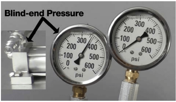
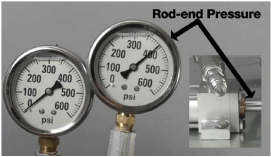
The most accurate method for calculating cylinder force is to measure pressure on both the blind-end (piston side) and the rod-end of the hydraulic cylinder.
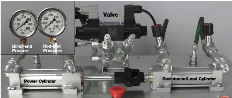
Illustrated above is how to measure pressure on both the blind-end and rod-end of the hydraulic cylinder.
These pressure measurements can then be used calculate force on each side of the cylinder. Subtracting the blind-end force from the rod-end force will provide the output force of the cylinder (see formula in the example below).
Taking a video of both pressure gages during the process enables accurate viewing of the highest and lowest pressure readings during the actuation process for formula conversion. View our video on How to determine force in a hydraulic system.
Example:
This application has a 3.5” (100mm) bore cylinder with a 1.5” (45mm) rod operating with a servo-hydraulic valve. During the cylinder’s extend stroke, the max pressure seen is 1,500 PSI (103 Bar). On the rod end of the cylinder, the down-side (or return line to the reservoir) pressure is 1,000 PSI (69 Bar). Utilizing the force differential pressure, we can determine the required extend thrust by the following formula:
Force = [A1 x P1] – {A2 x P2]
Area = π x r2
A1= Piston surface area
A2= Effective surface area of cylinder
P1= Blind-end (piston side) pressure (PSI) or (Bar)
P2= Rod-end pressure (PSI) or (Bar)
r = Radius of bore or shaft size
For area 2, first calculate the piston surface area then subtract the rod area. This ensures only the force on the effective surface area contacted by oil within the cylinder is being calculated. Plugging in the application values as follows:
A1= [(π x 1.752)
A2= [(π x 1.752) – (π x 0.752)]
P1=1500 PSI
P2= 1000 PSI
then
[(π x 1.752) x 1500] – {[(π x 1.752) – (π x 0.752)] x 1000}
Force = (9.62 x 1500) – (7.85 x 1000)
Once the area of each cylinder end is determined, the final steps of multiplying area by pressure and subtracting the difference gives us our force estimate:
Force = 14430 – 7850
Lbf Force = 6580
kN Force = 29.28 kN (metric equivalent)
By taking into account the effective rod-end area and reactive force, the final calculation has been significantly reduced. Taking pressure times the area of the piston alone would have generated a result of 14431 lbf or 64 kN. Selecting one or even two bore sizes larger in hydraulic cylinders does not have a dramatic impact on the total cost of components within a hydraulic system. Utilizing this same practice for an electromechanical system has an significant impact on system cost.
To better illustrate how the method used can impact the end result when converting a hydraulic cylinder to an electromechanical one, let’s compare three possible outcomes for force calculations with this same example.
OPTION 1 – SYSTEM PRESSURE AND PISTON AREA ONLY:
Force = Area x Pressure
Force = (π x 1.752 ) x 2500
Force = 9.62 x 2500 Lbf
Force = 24,050 kN
Force =107.02 (metric equivalent)
OPTION 2 – WORK PORT PRESSURE AND PISTON AREA ONLY:
Force = Area x Pressure
Force = (π x 1.752 ) x 1500
Force = 9.62 x 1500 Lbf
Force = 14430 kN
Force = 64.21 (metric equivalent)
OPTION 3 – WORK PORT DIFFERENTIAL PRESSURE/FORCE CALCULATION:
Force = (A1 x P1) – (A2 x P2)
Force = [(π x 1.752 ) x 1500] – {[(π x 1.752 ) – (π x 1.752 )] x 1000}
Force = (9.62 x 1500) – (7.85 x 1000)
Force = 14,430 – 7850 Lbf Force = 6580 kN
Force = 29.28 (metric equivalent)
The change between option 1 & option 2 is a 40% reduction in force, while the variance between option 1 & option 3 is over 70%! This highlights how using system pressure and piston area alone significantly affect estimated forces. In applications where there is a high return pressure back to the valve from a hydraulic cylinder (commonly seen in servo-hydraulic applications), understanding the forces at play on both sides of the cylinder will bring the force requirement down to accurate levels in order to properly size a servo motor, gear box, and electric actuator. Failing to account for back pressure and rod diameter with higher back pressures, may result in an oversized electric actuator, creating a costly solution that can affect the application’s return on investment.
In order to ensure you select the right electromechanical actuator alternative, how you measure the force of the hydraulic cylinder is key. Never use the rated system pressure in the force calculation as it will result in oversizing an electric actuator resulting in additional costs and challenging ROI. Measuring the work force differential output as close as possible to the hydraulic cylinder ports and at both ends of the cylinder will result in more accurate thrust force measurements ensuring the right electromechanical actuator is selected for the application.
This illustrates the difference in pressure output at the blind-end (piston end) and rod-end of the hydraulic cylinder and why not to use the rated system pressure in the force calculation.
Part 2: Motion Profile (Speed, Force, Dwells)
Converting a hydraulic cylinder in a machine process goes beyond determining the force of the application. Having a fundamental understanding of the process will continue to ensure that the final electromechanical system is optimally sized to replace the incumbent hydraulic system. Omitting what some would consider minor details can have a dramatic impact on not only the size of the mechanical actuator but also on the servo motor, gear reducer (if required) and servo amplifier leading to increased costs and potentially sub-optimized performance.
After calculating the force requirements as described in Part 1 of this guide, breaking down the motion profile and the loading profile will begin the process of framing up the requirements to properly select the motion control components.
Understanding the motion profile of the application is crucial to both the actuator and the servo motor. When specifying these components, Application Engineers will not only need to look at the peak requirements (for speeds and loads) but also need to understand the average or continuous rating for both these parameters. This will drive the selection process for an electric actuator system that is optimized for both the peak and continuous rating of the application.
Both servo motors and drive screws (roller or ball) have peak and continuous operating regions that are designed and tested to keep the components within temperature limits with respect to achieving desired life. Other considerations such as ambient operating temperatures and general environment may also have an influence in motor and actuator selection.
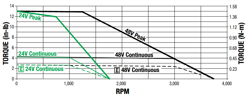
This chart shows the differences between a servo motors peak and continuous force ratings
Determining motion profile including peak, continuous speeds and forces
Motion control components can operate in the peak area of their ratings for brief periods of time throughout the process. However, during one complete motion cycle (extend, dwell, retract, dwell), the average speed and average force must fall within the continuous operating region of the components (power screw, servo motor, gearbox and servo drive). Exceeding the continuous operating region of any of these components can diminish the anticipated service life. Hydraulic applications, more often than not, will have pretty consistent speed in a given direction which makes determining the peak and continuous speeds pretty easy. By taking a video on a phone or using a stop watch application, the times for each move and dwell in the motion cycle can easily be recorded.
The dwells (when cylinder remains stationary) contribute to the average or continuous rating for both speed and force. Sizing an application without any of these dwell times will create very high speed and force averages resulting in an actuator or motor that may be grossly oversized for what the application would require.
By combining distance traveled with time it takes to complete the move, an application engineer now has everything to calculate peak (worst case) and continuous (average) speeds.
A common method for calculating this is as follows:
D = Distance of element
T = Time of element
Average Velocity = 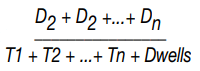
To determine the average load, one must determine the loading conditions throughout the entire cycle. Utilizing the differential pressure method discussed in the previous section:
Force = (A1 x P1) – (A2 x P2)
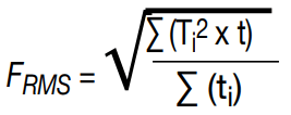
Once all the loading scenarios have been documented, the average force can then be determined with the following formula:
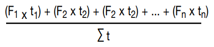
or more accurately
FRMS = RMS Force
Fi = Force during inverval i
∑ = sum
i = 1 to n
Once your average force and average velocity are determined. There are other considerations that may again help optimize the performance of the system. One of these is to look at the process itself to determine if there can be any improvements. It is not uncommon for hydraulic applications to cycle full stroke (extend and retract) during a given process. This may not always be the case when utilizing transducers or servo hydraulic valves but again, the process itself may benefit from improvements in better process control through utilizing the flexibility of the electric actuator system to fully control position, velocity,
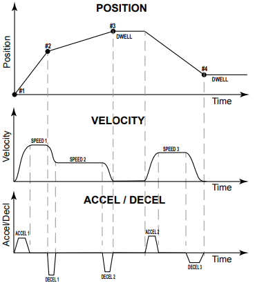
This chart shows different motion profile positions at different velocities with different accel/decel rates, all under full and precise control.
accel/decel and force. For example, an electric actuator may have to only extend and retract 1” or 25mm to perform a repetitive pressing application and then can do a full retract for changing tooling or servicing where as a hydraulic cylinder typically needs to run its full stroke length. By making process improvements such as this, it can minimize the required speeds and forces which further helps optimize an electric actuator solution.
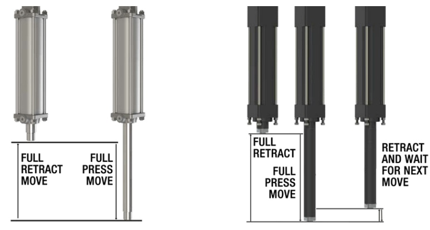
This illustration shows move comparison of a hydraulic press move on the left vs. electric press application on the right.
Other Motion Control Considerations
Additional characteristics of electromechanical actuators include variable speeds, acceleration/deceleration and force control. Electromechanical actuators utilize servo control which continuously monitors position, speed, acceleration and force/current. In applications requiring precise speed control, (such as dispensing fluids or pressing applications requiring two different speeds in the extend strokes), electric actuator systems are fully programmable, can improve process control and can help minimize cycle times and increases process repeatability significantly. With respect to acceleration/deceleration, electromechanical systems can fully control the starts and stops without introducing vibrations or shocks into the system that are common when hydraulics bang into a hard stop. This control of acceleration/deceleration not only improves equipment reliability, it can also be factored into improving the cycle time of the motion profile. Finally, electromechanical actuator systems also have full control over current which results in torque in the servo motor and force through the power screw. Electric systems can instantaneously control, change or ramp current to produce force in milliseconds whereas hydraulics typically require time to build pressure. By understanding the new capabilities and flexibilities of an electromechanical actuator system, processes can be improved and motion profiles (average force and average speed) can be reduced for the electric actuator system further optimizing size and cost of components.
By now the motion system is nearly complete. The forces required by an electromechanical actuator have been properly determined. Motion requirements (speeds & dwells) have been defined and any potential process improvements by utilizing the full capabilities of servo motion control have been identified. An appropriately sized actuator has been determined as have the motor requirements. The remaining steps are to determine the size motor, gear reducer (if necessary), drive voltage, and cabling to tie it all together. These topics will be covered in the third and final section.
Part 3: Technology Selection
With the forces and speeds determined, the actuator drive screw, servo motor and drive, and gearbox (if required) need to be selected to complete the motion system. In addition to sizing considerations, every application has different requirements for size, weight, life, environment and other factors that affect technology selection as well.
Technology Selection−Actuator
Electric actuators are available with several power transmission mechanisms. All of the application data is necessary to make an informed decision on which screw technology to implement. The application speeds, thrust, duty cycle, service life, and maintenance requirements should also be considered.
For example: if there is little to moderate load across most of the actuator’s travel with a very high load over a very small distance, the use of a planetary roller screw and an optimized motion profile can provide increased throughput and service life.
Below are some generalizations between three commonly found types of screw technologies available in rod style actuators for hydraulic replacement applications.
Acme/Trapezoidal Screw with Bronze Nut – Quiet, inefficient, and cost effective. These screws are well suited for applications that do not require high or continuous duty cycles. By design their low efficiency ratings (<40%) allow them to be self-locking and also general resilient to shock loads and vibration. In general these screws are best utilized for duty a duty cycle of 40% or less.
Ball Screw – Very efficient, low to moderate noise, low to moderate cost increase over Acme screws. By moving to recirculating, hardened balls rolling on a hardened screw, efficiency and performance are increased. The use of hardened steels also provide for a more consistent performance that can be estimated using how to calculate life (B10 and L10) equations. Careful consideration must be taken into account when using this screw type in applications where there is very small movements between loading cycles or where the potential for significant shock loading is high. These types of conditions can cause point loading and premature wear on the screw. Ball screws can be deployed in these applications but typically at the expense of increasing the size and capability to offset the increased stress. Use of a motor brake is also necessary to keep any loads from drifting or falling in the event of a power loss condition.
Roller Screw – High efficiency, low noise, moderate to high cost increase. Roller screws are commonly used for hydraulic replacement applications. Unlike ball screws, this technology uses a combination of rolling and sliding elements to better dissipate thrust loads. The increased surface area for load distribution makes them resilient to high stresses in a condensed area of repeated travel. They are also very power dense and provide the most compact actuator packaging to replace hydraulic cylinders. Roller screws also use hardened power transmission components which as with ball screws have a very predictable service life using life calculation (B10 and L10) equations. They are not quite as efficient as a ball screw but could still too require a motor brake to prevent a drifting or falling load.
Technology Selection−Motor/Drive/Gear Reducer
With larger hydraulic system replacements requiring high thrust forces, managing both the speed and torque required from the motor can at times be a bit of a give and take exercise. Large frame size servo motors will typically have very high torque at low speeds and RPM limitations of typically between 1500-3000 RPM as compared to smaller servos motors (less than 115mm frame) that have a typical range up to 6000 RPM. Finding the right ratio gearbox to minimize motor size and maintain speed requirements may take some patience and persistence to complete.
Consider the Following specifications when selecting these components
| SPECIFICATION | MOTOR | GEARBOX | DRIVE |
| Torque | X | X | |
| RPM | X | X | |
| Voltage | X | X | |
| Current | X | X |
It will be important to research each motor manufacturer to ensure that the desired size and series of servo motor is available with a motor brake when using ball and roller screws for vertical or fail in place applications.
By the time a motor is selected, there should be a sound understanding of the power requirements that will be needed from the servo drive. Most servo drive manufacturers have many sizes and power ranges to choose from. Making sure that all of the communication and functionality requirements are met will take more time to finalize than getting the power output just right. Other things to consider would be if the user wants a single-axis indexing drive which will require external logic control, a standalone single axis drive with varying degrees of logic control, or a multi-axis system which will require a multi-axis motion controller. Getting in touch with a motion control specialist or the manufacturer at this point of the design phase will help to zero in on the right choice to help select the desired drive/ controller.
Environmental Considerations
At each point of the design and component selection phase, the environment of installation location for the actuator, drive and cabling should be considered as part of the decision making process. Electro-mechanical actuators have proven themselves to be a very reliable part of an automated process in very harsh environments. The difference to having success or ongoing difficulties will be dependent upon adding the proper features for the application. There are a variety of different seals, coatings, gaskets, lubricants, and environmental provisions that will increase the service life of the actuator. Careful consultation with the actuator manufacturer or experienced motion control expert will again provide an efficient means of determining which options are appropriate for the application. Lastly, an understanding of if there are any hazardous location certifications may limit the availability of motors and in some cases mechanical options as well. In these circumstances, consulting with the manufacturer will help ensure the zone requirements can be met by each piece of the motion system.
Summary
Following the guidelines set forth in this guide will ensure that the electric actuator you select will be the most cost-effective solution and will perform consistently, efficiently and effectively for the longest period of time.
First, defining the amount of work the hydraulic cylinder is performing and the cylinder’s force is key to determining the correct electric actuator size to select. It will also impact the rest of the motion system performance. Second, understanding the motion and loading profiles will allow the proper motor and drive selection for optimal actuator performance. Third, determine the best electric actuator technology to match your application parameters by selecting the right screw choice and determine the motor/ drive/gear reducer that is the best fit to maximize performance. Then, review any environmental or safety concerns the application will require and discuss with the actuator manufacturer to ensure all the selected components of the motion system are capable of operation in the specified conditions.
The time taken up-front to define all these variables will provide an optimized electromechanical actuator solution sized to system requirements and a motion system that will perform as expected.