 Ask an Engineer
Top 5 best practices for designing electric actuators into food processing equipment

by Andy Zaske; VP of Sales and Marketing and Sean Halverson; Mechanical Engineer
Introduction
Food manufacturers are demanding cleaner, safer machine designs from their OEM machine builders. Machine designers must be familiar with current best practices for hygienically designed food-processing equipment. In this paper we explore best practices for designing and installing electric actuators in food processing equipment to help create open/clean-in-place designs that reduce the risk of bacterial contamination and improve overall cleanliness of machine designs.
Machine designs continually evolve to meet manufacturers’ requirements for increased automation, less production waste, greater efficiencies and, overall, reduced cost. In addition to these criteria, machines used for food processing increasingly must be designed to meet ever-stringent requirements to keep food clean during production and ensure it arrives safely to the consumer. Standards such as EHEDG, 3A, USDA and others define hygienic design principles for machines and components to prevent bacterial contamination of the food and beverage products.
Food processors understandably want to reduce—and preferably eliminate—food-recall incidents, mostly because the incidents pose a threat to their customers, and also because recall incidents are expensive (due to fines, recalls, law suits, adverse publicity and lost production). As a result, food manufacturers are demanding cleaner, safer machine designs from their OEM machine builders. This trend is especially true for higher-risk processing environments, such as meat, cheese, dairy, seafood and poultry. Food processors also require new automation ideas to increase employee safety and efficiency. In the era of social distancing, that means minimizing their contact with food production and each other.
Automation plays a key role in keeping facilities safe and productive. Actuators in particular, because they are the primary linear mover, affect efficiencies in food-processing applications and are specially designed to help manufacturers maintain the highest standards for health and safety.
The manufacturer of this volumetric piston filling equipment, used a hygienic electric actuator for accuracy and ease to adjust for product changeovers
Machine designers can meet manufacturer expectations and comply with food-safety standards by applying best practices for specifying electric actuators in food processing equipment. These design principles create open/clean-in-place designs that reduce risk of bacterial contamination and improve the overall cleanliness of machine designs. Along with best-practice design, it is always a good idea to consult with EHEDG, USDA, or appropriate governing agencies to ensure compliance of a design.
This paper explores best practices for designing and installing electric actuators in food processing equipment in the following areas:
- Selecting hygienically designed actuators
- Designing the actuator into your open architecture machine/system
- Installing and handling electric actuators
- Maintaining and cleaning actuators
- Comparison of integrated motor and non-integrated actuator designs
Current machine design practices and existing actuation technologies
Some machine builders already utilize hygienically designed automation components, but more often, legacy machines are adapted to meet the increasingly stringent health regulations. For example, automation components are often housed in stainless steel protective enclosures to protect the components from water, chemicals or food products. Or, components are coated in epoxy or painted with food-grade paint. Components requiring washdown are often “bagged’ to protect against ingress. All of these techniques add cost to the process and introduce greater risk. Protective enclosures require additional maintenance and increase machine cost; epoxy or paint is subject to chipping and wear, requiring frequent examination and replacement; “bagged” components require extra time and are subject to increased contamination risks.

Three unsatisfactory methods (and their problems) for protecting equipment during washdown include: 1. Stainless steel enclosures are too bulky and expensive; 2. Epoxy painted components may chip and any chips need to be tracked for the life of the product. 3. Covering motors and actuators with bags is time consuming, risks water damage and can be less effective for maintaining sanitization.
Fluid power drawbacks
Some fluid power cylinders are hygienically designed for food processing: water-tight construction prevents ingress; stainless materials prevent corrosion. But fluid power systems that use pneumatic or hydraulic cylinders may create contamination risks.
Pneumatic cylinders require a clean, filtered and dry air system to prevent condensation. Bacteria thrives in wet, damp areas, and it is difficult to monitor or prevent condensation in the vast compressed air systems found in food and beverage processing plants. Frequent washdowns create hot and cold cycles that typically cause condensation. Pneumatic cylinders also typically only have two positions and require manual adjustments for charges in stroke for flexible manufacturing.
Hydraulic cylinders can leak high pressured hydraulic fluid and contaminate the food product. Oil is slippery; leaks create safety concerns and are difficult to clean up. Hydraulic cylinders can be deployed with food grade oil, but these oils are often used in the system for long periods of time and then can become dirty.

Preventing a major contamination event by replacing fluid power cylinders with electric actuators justify the ROI.
Fluid power cylinders rely on wearable seals for operation and containment. Oils circulated at high pressures create stress on seals and hoses around the entire system. These seals require constant scrutiny and periodic replacement for consistent operation and to prevent fluid leaking from the tubing and cylinders.
In contrast, electric actuators mitigate the risks associated with fluid power systems and offer a clean technology for hygienic, sanitary environments. Preventing just one contamination event by displacing fluid power cylinders could justify the ROI for the food producer. Continuing advances in electric actuators are making them the technology of choice for an increasing number of food applications.
1. Selecting hygienically designed actuators:
Food processing facilities encompass a variety of manufacturing spaces. These areas include:
- Raw materials storage (dry side)
- Food contact / wet processing areas (wet side)
- Filling and packaging (wet side)
- Material handling, storage and shipping (dry side)
For the ‘dry side’ manufacturing areas, general industrial-grade electric actuators with exterior components made of anodized aluminum or painted steel will satisfy processing requirements. However, the ‘wet side’ areas have the biggest impact on quality and require rigorous cleaning and sanitizing: These areas are also subject to the most scrutiny by the regulatory authorities.
The most critical food and beverage processing applications involve dairy, meat, seafood, and egg production. Food contact / wet processing areas require actuators that are built from proper materials and seals, constructed for easy cleaning and are able to operate in specified temperatures.
Proper Materials:
Automation components made of non-compliant material may corrode and shed particles into the processing environment. Stainless steel is corrosion-resistant, withstands tough processing conditions and complies with industry standards . A variety of stainless steel alloys can be used in the food processing environment. Best practice in hygienic design for linear actuator bodies, motor housings and fasteners is to use type 316/316L due to its superior corrosion resistance characteristics. Type 304/304L stainless is also used in some cases.
Metal alloys other than stainless steel (such as aluminum) may be suitable under certain conditions. Avoid alloys containing lead, leachable copper or other toxic metals.
EHEDG “Hygienic Equipment Design Criteria” Doc 8 April 2004
- “Where good resistance to general atmospheric corrosion is required, but the conditions of intended use will involve only solutions with pH of between 6.5 and 8, low level of chlorides (50mg/l) and low temperatures (25°C), the most common choice would be AISI-304.”
- “If both the level of chlorides and the temperature exceed approximately double these values, the material will require greater resistance to the crevice and pitting corrosion which may result from chloride concentration locally. The addition of molybdenum to AISI-304 (creating AISI-316) improves its corrosion resistance….”
- 316 is sufficient for temps up to 150° C
Generally, a number 4 ground finish, or better, on stainless steel that is free of pits, cracks, folds or other imperfections is suitable for washdown applications. For welded junctions, electro-polishing, glass beading and shot peening are not generally acceptable alternatives to a number 4 ground finish.
Proper Seals:
Electric actuator rod seals are integral to actuator performance and must be made of durable material that withstands operating conditions. They are usually made of Viton® or Ultra High Molecular Weight (UHMW) polyethylene to meet ingress protection requirements for washdown and corrosion resistance. For these reasons, seals are designed to numerous material properties and characteristics including temperature rating, compressibility, resistance to cracking, wear and sanitary chemicals, hydrophobicity, clean ability, regulations and color.
When selecting a linear motion component, it is important to validate that the manufacturer factors in seal interference and friction when approving the motion profile and life estimates. Friction between the rod seal and rod can damage the rod seals. Design engineers should research the material composition of all polymers used in the design to ensure FDA-approved seal materials are used.
IP69K is the best practice for the food and beverage environment. The most challenging area of IP69K design is the seal on the thrust rod. Seals wear during operation, and a proper seal design is essential to meet and maintain the IP69K specification. Seals with tight dimension tolerances assure a correct fit on the thrust rod and the durability to withstand the many extend/retract cycles.

Care must be taken to ensure seals are not damaged in any way during installation.
Seals will eventually require replacement. Seal manufacturers generally provide guidelines for replacement frequency, but how fast a seal actually wears depends on many factors. These include frequency of motion, alignment, cleaning and sanitizing chemical compatibility, and cleaning frequency. General guidelines for seal replacement include:
- Replace seals every 25 million inches of travel.
- Replace seals more frequently (i.e., twice as often as manufacturer recommendations)
- if food product is expected to be present on thrust rod during operation
- if washdown frequency is 3+ time per day
- if high-sanitizing chemical concentrations are used.
- Rinse seals after sanitizing to remove residual sanitizing chemicals and extend seal life
- Re-lubricate rod seals periodically with proper grease to extend seal life
- Visually inspect the thrust rod and front seal periodically
Constructed for Easy Cleaning:
Actuators designed with domed or rounded bodies, rounded edges and a smooth finish prevent moisture, food particles and microorganisms from collecting and pooling. Particles and sanitary solutions easily drain off, improving the washdown process and minimizing the chance that contaminates will linger on the actuator after cleaning.

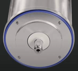
The round body, smooth finish and food grade seals make the design of the IMAS actuator optimized for washdown.
Even motor housings should be rounded to promote runoff. A properly designed electric hygienic actuator has no sharp edges or angles (<= 90 degrees) and no flat surfaces (even transition features should have a radius of >=6 mm.) that could create edges or pockets where food can lodge and inhibit the cleaning process.
Operating Temperatures:
Ambient temperatures during food processing can range from warmer environments to cold refrigerator or even freezer environments. Several cold-warm-cold temperature cycles can occur every day, depending on the temperature of the environment, the temperature of the equipment and the temperature of the water (up to 176F / 80C) used in the cleaning process. These variations may create condensation and/or pull vacuum on sealed equipment due to fluctuating pressures. In these environments, the combination of an IP69K design and a breather/purge port becomes essential to prevent moisture ingress.
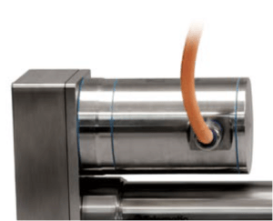
Breather port best practices:
A breather port is located in the back of the actuator adjacent to the cable(s). Correctly utilized, the breather port should will prevent against ingress of moisture by equalizing pressure in the actuator during operation and temperature fluctuations. An IP69k face seal fitting is required. The air supplied or exchanged should be dry and clean, and the air line periodically inspected for moisture and sanitized as required.

Breather port on IMAS actuator.
2. Designing the actuator into your open architecture machine/system:
Keep in mind some design best-practices will help machine designers achieve results specific to their requirements.
Stainless steel actuator design allows an open-frame architecture for the whole machine. It answers the on-going question of what might be growing inside the “box.” Large stainless enclosures can be eliminated or minimized, improving cleaning and ensuring the design will be approved by regulatory agencies.
Alignment and compliance
Correct alignment of the actuator with respect to the application load and axis of motion is essential to minimize side loading. The extended rod and rod seals are subject to wear or damage under even moderate side loads. The actuator rod must be guided or supported to minimize side loading. Loads should be aligned in parallel with the line of motion of the thrust rod.
It is important to create some level of compliance in at least one of the two attachment points for the actuator. Despite all best efforts there will likely be some variation in components and allowing the motion of the actuator to have some movement (compliance) will help avoid any possible binding or side loading. There are several ways to mechanically create this compliance:
- Clevis
- Spherical rod eye
- Trunnions
Actuator orientation on the machine design is important and some orientations will create challenges with cleaning.
Recommended actuator thrust rod orientation is down or horizontal. Due to increased
risk of contamination and ingress never orient the actuator with the thrust rod up.
Integrating servo motors with hygienic actuators:
General classes of servo motors used in hygienic applications:
- White epoxy painted, typically IP67 environmental rating: Suitable for dry non-contact areas rarely subjected to wash down. Their environmental sealing, epoxy paint, and nickel plated connectors do not stand up well to common sanitizing solutions applied with high pressure sprayers. The epoxy paint can flake off, sanitizing solution can enter through shaft seals, and nickel plated connectors discolor from oxidation.
- Stainless steel, typically IP69k rating: Motors that carry the IP69K rating are ideal where hygiene and cleanliness are critical, as they are proven to be durable and resistant against water, chemicals, high pressure, and high temperatures associated with demanding cleaning and safety measures.
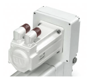
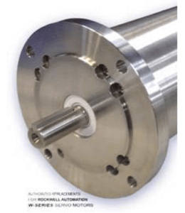
- Flanges available on hygienic motors: C-Type flange: (Rockwell VPH shown) which is easier to seal, easier to clean, reduces areas for harborage, and should include an FDA compliant O-ring. Before choosing a C-type flange motor, make sure the motor supplier provides an O-ring (some motor suppliers force the user to source the o-ring separately). D-Type flange: (Elwood W-Series shown). Difficult to seal and clean. Frequently do not provide o-rings or gaskets and just suggest using RTV to seal the motor-to-actuator interface.
Cable management:
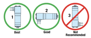
Over time, liquid contaminants such as oil and cleaning solutions may accumulate on the cables and onto the cable glands. To minimize the introduction of contaminants to the cable glands, mounting the actuator with the cable gland down is best. Mounting with the cable gland to the side requires a bend or drip loop. It is not recommended to the mount the actuator in an orientation that faces the cable gland upwards. If mounting the actuator with the cable gland facing upwards is unavoidable, the cable should be routed with a drip loop prior to entering the cable gland. Examples are shown depending on the orientation of the cable glands. Units mounted with the cable glands on the bottom surface of the actuator require no looping.
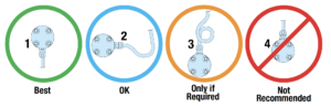
1. Preferred cable gland orientation is below the actuator and does not require loops or bends. 2. Cable glands at the side requires bends or loops in the cable. 3. If the cable glands must be at the top of the actuator a loop in the cable must be added. 4. Cable glands at the top without a loop are not recommended.
3. Installing and handling electric actuators:
Once the proper actuator has been selected, ordered and manufactured, it is critical that the actuator is handled properly during installation. Special care needs to be taken as soon as the package is opened.
- Carefully remove linear actuator from package. *Consider the weight of the actuator to determine how to best move it.
- Visually inspect the actuator for damage and notify the carrier or manufacturer of any shipping damage immediately.
- If the actuator is mounted in a vertical or inclined (sloping) position, include safety measures that control the work load in case of a screw failure.
Don’t use cables for lifting points:
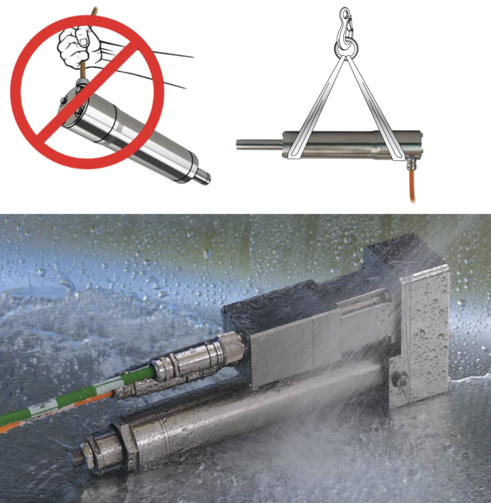
Be extra careful with stainless steel. It is a great metal for surviving corrosive environments, but it is surprisingly soft. Handle with care to avoid easily damaging the surface finish.
| BALL SCREW LUBRICATION (Example Calculation)
Step 1: Calculate your actuator’s power output.
|
| ROLLER SCREW LUBRICATION (Example Calculation)
Step 1: Select the Basic Lubrication Interval (tBL) based on the cycles RMS Velocity (VRMS)
|
4. Maintaining and cleaning actuators
Most electric actuators, if designed and deployed properly, will require only minimal maintenance. However, actuators used for food-processing applications do require extra attention.
Proper sealing on actuators is critical for keeping water and cleaning solutions out of the interior of the actuator. For seal replacement recommendations please refer back to ‘Selecting Hygienically Designed Actuators’ section above.
Lubrication
Actuators will typically have been lubricated at the factory and are ready for installation. The internal screw will require re-lubrication at pre-determined intervals. See the lubrication interval calculations listed below for schedule estimates. Use caution when adding grease; overfilling can cause excessive heat build-up and affect performance and potential premature failure. Screw lubrication will vary greatly by manufacturer. Some manufacturers provide optional lubrication ports on the thrust tubes or bodies of their stainless actuators.
Cleaning
Cleaning should only be done by qualified personnel. The actuator should be stationary and de-energized during cleaning. It is recommended that the actuator be fully retracted during cleaning.
Follow IP69K washdown standards for pressure, proximity and temperature. Violating the IP69K standards could reducing the operating life of the actuator. Most manufacturers recommend against or prohibit the use of friction-style cleaning, such as a wire brush. Washdown and wipe-down cleaning are the only approved cleaning methods.
Use only the minimum acceptable concentrations of cleaning chemicals to successfully sanitize equipment. Consult the manufacturer for chemical compatibility. Rinse the actuator after the cleaning process to minimize seal exposure to sanitizing chemicals.
5. Comparison of integrated motor and non-integrated actuator designs:
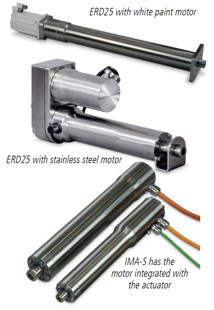
A key decision to be made by the design engineer will be the choice of using an integrated motor/actuator design versus a more traditional non-integrated design where the motor is a separate component that is attached prior to installation on the final machine. In a non-integrated approach you can use an in-line motor mounting configuration or a reverse parallel (RP) design. In the reverse parallel design the motor is mounted parallel to the actuator and uses a belt and pulley or geared system to transfer power. This RP design allows a much smaller footprint but does have some significant cost adders.
An integrated actuator and motor single piece design eliminates typical seals between the motor and actuator in a non-integrated design. This reduces the number of points for possible moisture ingress or bacteria harborage. It also eliminates the risk of seals being ripped or off center when installed.
| Differentiation Specification | Traditional | Integrated |
| Ease of Integration | Matched moter set | |
| Motor mount, envelope & weight | More compact overall & lighter weight | |
| System Costs | Competitive & no motor mount time | |
| Ingress protection | Motor mounting | |
| Maximum stroke | Better screw support | |
| Anti-rotate | Standard, internal | |
| Efficiency & reliability | Fewer torque components & bearings | |
| Positional accuracy & repeatablity | Rigid coupling, aligned | |
| Force capacity | Motor flexiblity for more applications | |
| Force reapeatability | Rigid coupling, lower torque ripple | |
| Continuous/peak force ratings | Motor/screw heat are separated | |
| Acceleration & responsiveness | Higher resonant frequency, stiffness | |
| Shock & vibration | Closer center of gravity, rigid coupling | |
| Safety (vertical loads) | Belt or coupler breaking | Rigid coupling |
Summary
Modern food-processing equipment must comply with strict health and safety hygiene standards required by the EHEDG, 3A, USDA, FSMA and others. To comply, and to reduce food-safety incidents as much as possible, food manufacturers require cleaner and safer machines from their OEM designers. Actuators are key components that affect a machine’s safe and sanitary operation. There are several criteria for selecting compliant actuators. Best practices for designing actuators in food-processing equipment, especially equipment used for meat, cheese, poultry and seafood processing, include selection, specification, installation, maintenance and cleaning. These design principles create open/clean-in-place designs that reduce the risk of bacterial contamination and improve overall cleanliness of machine designs.