 Ask an Engineer
Pneumatic rodless actuators: The 10 most common sizing mistakes and how to avoid them
This paper is a result of the knowledge gained through decades of rodless cylinder application experience. We actively track the most common mistakes our customers encounter when sizing rodless linear actuators. This paper focuses on pneumatic rodless cylinders (specifically band type) and is the first in a series of topics on the sizing and selection of rodless linear actuators/cylinders.
In 1955, Tolomatic was the first to introduce rodless technology to the U.S. market with the introduction of the cable cylinder, and has built a reputation for being the rodless leader in linear motion control.
Mistake #1: Overestimating the available air pressure
Overestimating the available air pressure can cause a loss in actuator performance or possibly a complete malfunction. The best solution is to check your air pressure with a gauge to get an accurate reading and build in safe engineering practices. For example, a plant may supply 100 PSI of pressure but at different locations in the plant, pressure can fluctuate as much as 10% due to variable demand cycles. This means the “actual available air pressure” is only 90 PSI.
A 5 to 10% fluctuation in air pressure is quite common and can make a big difference in selecting the proper cylinder for an application. It is always best to factor in a 10% pressure loss factor from the gauge air pressure.
Mistake #2: Incorrectly determining the actuator’s working stroke and overall length
There is a portion of the actuator stroke that cannot be used due to the interference of the internal components and the room needed to physically come to the end-of-stroke. This is normally referred to as the actuator’s “dead length.” This dead length is determined by the manufacturer and should be indicated on the dimensional information for each specific actuator.
To properly determine the actuator’s overall length (OAL), you must know the distance of travel (working stroke) and add this to the given dead length at each end of the actuator. Keep in mind that the addition of auxiliary carriers and other actuator options will add to the actuator’s dead length. For example, for a Tolomatic cylinder with two carriers, add the total dead length, working stroke and the distance between the center of carriers to determine the cylinder’s OAL. It is important to reference the dimensional information provided by the manufacturer when ordering options toproperly determine if additional dead length is required.
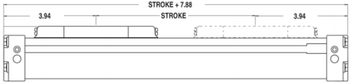
In the illustration below, the non-working (dead) space required by the mounting and carrier mechanisms is defined as 3.94 inches at each end of the actuator. In this case, the actuator requires 7.88 inches of total dead space. This dead space needs to be added to the desired working stroke requirement to determine the overall actuator length. In this example, the actuator needs to have a working stroke of 16.12 inches. To determine the overall length, take the working stroke (distance of travel) plus the total dead length.
Working Stroke (16.12 inches) + Total Dead Length (7.88 inches) = Overall Length (24 inches)
Mistake #3: Under or over sizing the cylinder
When it comes to cylinder sizing, bigger is not necessarily better. It can end up costing more in money and air consumption. On the other hand, under sizing a cylinder may save a few dollars but it will not provide optimal application performance or the appropriate operational safety factors. The most productive application performance is achieved when the actuator is properly sized based on load, force, and bending moment performance capacities with a safety margin factor.
To properly size a cylinder, you will need to know the following application requirements:
- Available air pressure
- Magnitude of load
- Orientation of load (location relative to cylinder carrier)
- Final velocity of mass attached to carrier
- Working stroke length
- Cycle rate
- Cycle time
- Center of gravity of load in relation to the cylinder’s load carrying device
- Orientation of the actuator
Once these factors are known, it is necessary to determine the cylinder’s load (thrust) force capacity based on the indicated available air pressure. The cylinder should perform within the specified capacity range. If the application requires performance at the maximum level for that cylinder, either a larger bore size should be considered or a different cylinder style with higher capabilities.
Once the bore size is determined, the magnitude and orientation of the load also needs to be considered. Often, a cylinder is selected based only on the force it can produce. If a load is to be supported by the actuator, it is important to know the bending moment capacity of the cylinder’s bearing and load carrying system in order to determine if it is capable of performing consistently under the load requirements. Dynamic moment loading should also be taken into consideration when determining the force requirements. Refer to Mistake #5: Overlooking the effects of dynamic loading. Selecting the wrong cylinder can result in poor performance, reduced life, excessive component wear and/or cylinder failure.
Mistake #4: Not considering the effects of resulting moments (torques)
The position and size of the load on the cylinder determines the resulting bending moments applied to the cylinder itself. Even if a load is located on and directly over the center of the load carrying device, it will still be subjected to bending moments on acceleration. Refer to Mistake #5: Overlooking the effects of dynamic loading. It is important to determine if the cylinder is capable of handling the resulting moments. For off center or side loads, determine the distance from the center of mass of the load being carried to the center of the cylinder’s load carrying device and calculate the resulting bending moment.
EXAMPLE: Distance of center of mass of the load from the center of the cylinder’s load carrying device = 3 inches. Load being carried is 30 lbs. My = 3 inches x 30 lbs = 90 in-lbs.
MOMENT DIRECTIONS
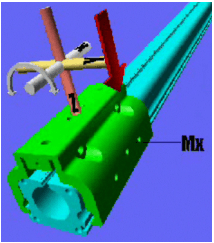
Mx Moment (Roll)
Mx moments are created by loads applied at a distance from the “x”axis. An example is an over hung load that is centered off to the side of the cylinder’s load carrying device. Mx moments create a rotation around the “x”axis. The red arrow indicates the direction of the resulting “roll” motion on the cylinder’s carrier and bearing system. The farther away the load is from the center of the cylinder’s load carrying device, the larger the resulting moment.
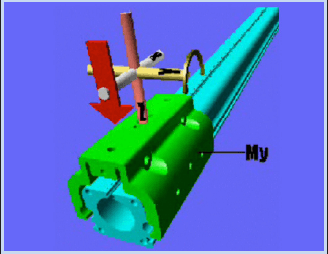
My Moment (pitch)
My moments are created by loads applied at a distance from the “y” axis. My moments create a rotation around the “y” axis. The red arrow indicates the direction of the resulting “pitch” motion on the cylinder’s carrier and bearing system. The farther away the load is from the center of the cylinder’s load carrying device, the larger the resulting moment.
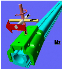
Mz Moment (yaw)
Mz moments are created by loads applied at a distance from the “z” axis. Mz moments create a rotation around the “z” axis. The red arrow indicates the direction of the resulting “yaw” motion on the cylinder’s carrier and bearing system. The farther away the load is from the center of the cylinder’s load carrying device, the larger the resulting moment.
Published bending moments are usually a maximum and assume only one type of moment is being applied. In certain applications, compound moments (which involve two or more of the moments described above) can occur. Each need to be evaluated and calculated per the manufacturer’s equation to determine if the cylinder is capable of the combined moment force.
Mistake #5: Overlooking the effects of dynamic moment loading
Unlike rod style cylinders, many rodless cylinders must support the load during acceleration and deceleration at each end of stroke. When there are side or overhung loads the dynamic moments must be calculated to determine which rodless cylinder is best equipped to handle the resulting forces.
DYNAMIC LOADING
The following illustrations (viewed from the top of the cylinder) show the effects of dynamic loading to the cylinder and its load carrying device. This condition occurs at deceleration (end of stroke) and acceleration (beginning of stroke.)
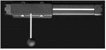
In the first illustration, the ball represents an overhung side load exerting a Mx moment on the cylinder’s carrier.
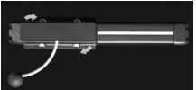
The second illustration shows what happens when the cylinder reaches one end of its stroke. When the carrier stops, inertia keeps the load moving forward, creating a dynamic twisting moment (Mz) on the cylinder.
The same thing happens when the cylinder cycles to the other end of stroke. The resultant dynamic moment may exceed the rated capacity of the actuator. After repeated cycles, the actuator may not achieve its designed life expectations if not properly selected.
Shock absorbers (mounted on the cylinder) are normally used in such applications to help compensate for the inertial effects of dynamic loading. In addition, it is recommended that a stopping device be placed nearest to the center of gravity of the moving load. For additional information on this topic, reference Mistake #7 – Incorrectly determining the cushion or shock absorber capacity.
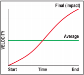
Mistake #6: Not understanding the importance between average and impact velocity
Velocity calculations for all rodless cylinders need to differentiate between average velocity and impact velocity.
Example: Stroking a 24-inch actuator in 1 second yields an average velocity of 24 inches per second. To properly determine the inertial forces for cushioning it is important to know the final or impact velocity.
A reasonable guideline for determining the final (impact) velocity is 2 x the average velocity (2 x 24 in/sec = 48 in/sec impact velocity).
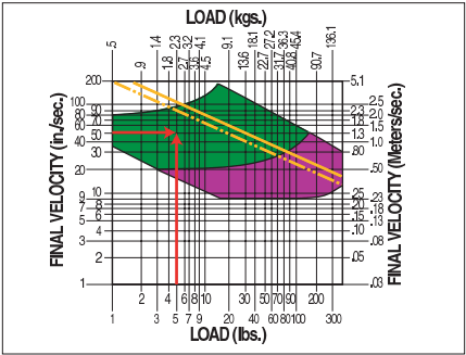
Mistake #7: Incorrectly determining the cushion or shock absorber capacity
Most rodless actuators are equipped with internal devices to help cushion the load at end of stroke. It is important that the final or impact velocity is known in order to determine the cylinder’s cushioning capacities. In the chart shown here, the final velocity has been determined to be 50 inches per second and the load being moved is 5 pounds. The intersection of these two points indicates that the level is within the cylinder’s cushion capacity, which is indicated by the yellow lines. Consideration now must be given to load position and the resulting moments exerted on the cylinder, (refer to static and dynamic moments in Mistakes 4 and 5) to determine if shock absorbers or external load stopping devices are required.
In the following example, the cylinder is carrying a 10 lb load and traveling at a final velocity of 80 inches per second when coming in contact with the shock absorber located at the ends of the cylinder stroke. The load must be stopped within the shock absorber stroke of 0.50 inches. The Mz and equivalent force applied to the cylinder’s load carrying device need to be within the limits of the cylinder’s rating capacities.
To determine this:
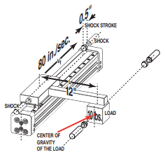
Mz = moment about z-axis
Vf = velocity (final)
a = deceleration rate
g = 386.4 in/sec2 (standard gravity)
s = shock stroke
P = Load
L = distance of load from cylinder’s load carrying device
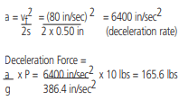
Therefore, the Mz created during stopping is:
Mz = (equivalent force) x L = 165.6 lbs x 12 inches = 1987.2 in-lbs
If the final velocity cannot be accurately determined, the use of limit switches with valve deceleration circuits or shock absorbers should be considered.
Mistake #8: Not factoring in the effects of motion lag due to breakaway, acceleration and friction forces.
It is important to understand how other forces and losses affect the total force required to produce the desired motion.
Total force calculation considering all sources of forces and frictional losses: Ft (total force) = Fa (acceleration force) + Ffr (forces due to friction) + Fbk (breakaway force)
Breakaway Force — Every rodless cylinder requires a certain amount of energy or force in order to move itself with no load attached. This force is referred to as the breakaway force. When reviewing the performance information for the cylinder, be sure that breakaway force is accounted for in the calculations (Tolomatic does factor this into published performance information.) In pneumatic applications, it is best to have excess force available to assure reasonable acceleration is achieved.
Acceleration Force –The amount of force required to accelerate a mass is typically larger than the force required to keep the load in motion. When selecting an actuator, the breakaway force of the cylinder and the frictional drag of the load must be added to the acceleration force requirements.
Friction forces occur when two materials slide across each other’s surface. The level of friction present between the two materials is defined by a numeric value called the Coefficient of Friction (COF). The COF value will vary depending on the material and the surfaces it comes in contact with and the type of friction (sliding or rolling) being generated. Engineering reference tables list the different coefficient of friction values for a variety of materials. They should be used to determine the COF for materials and surfaces used for specific applications.
For horizontal applications, to determine the force required to overcome the friction, multiply the mass (weight) of the load by the coefficient of friction.
Ffr (forces due to friction) = µ (coefficient of friction) x WL (weight of load)
| EXAMPLE COEFFICIENTS | FORCE REQUIRED TO OVERCOME STATIC FRICTION @ 100 lbs | |
|---|---|---|
| Steel on Steel | 0.58 | 58 lb |
| Plastic on Steel | 0.15 | 15 lb |
| Ball Bearing | 0.001 | 0.1 lb |
Mistake #9: Vertical vs horizontal applications
When a cylinder is mounted vertically in an application, there are additional force, load and air considerations that must be addressed. A cylinder mounted vertically needs to overcome the force of gravity first before it can accelerate a load upward. A vertically mounted cylinder will need to produce more force than a horizontally oriented cylinder to achieve this. In vertical applications, it is best to size a cylinder capable of twice the required horizontal force.
In addition, certain types of pneumatic rodless actuators may experience some degree of air leakage. If the actuator is required to hold a load vertically for any length of time, the amount of air leakage can effect how well that position can be maintained. In certain circumstances, some other type of holding device (such as a brake) or external guidance system may be required to safely control the load. Keep in mind that vertical applications with externally guided loads still experience moment loads due to the affect of gravity. For example, a 50 lb load with a bracket arm 12 inches from the actuator’s load carrying device would be subjected to a 600 in-lb moment load.
Mistake #10: Underestimating the effects of the environment
Failing to factor in environmental considerations may lead to catastrophic results. Extremely hot or cold temperatures, external abrasives, dirty or wet conditions, caustic fluids and air quality are just a few of the environmental conditions that can affect cylinder life. The effects of friction wear (abrasive, pitting, adhesive and corrosive) due to particulates or fluids coming in contact with the cylinder can cause premature wear, increased maintenance and possible equipment failure.
Most manufacturers specify a cylinder’s performance based on normal operating conditions. If the cylinder is to be operated in adverse environmental situations, it is best to discuss this with the manufacturer to determine if the cylinder is capable of delivering the expected performance.
Summary:
There are many important points to consider when sizing rodless cylinders. Knowing your available air pressure and determining the proper working stroke and overall length are relatively simple procedures. Others, such as determining the effects of moment loads, dynamic loading and breakaway pressure, can be more complex. For this reason, some manufacturers (Tolomatic is one) offer sizing and selection software that make it easier to select the appropriate cylinder. The software offered by Tolomatic factors in the breakaway force and automatically calculates the bending moments based on the speed values entered. It is difficult to determine inertia generated by a moving load by looking at static catalog tables. Software uses travel distance and speed values to determine the effects of inertia on a moving load. At the end of the sizing process, the result is list of cylinders that will fit the application requirements.
When using a manufacturer’s software product or manually sizing a cylinder, it is always best to discuss your sizing results and application requirements with the manufacturer or sales representative. Determining the right pneumatic rodless product can be an in-depth process because there are many different styles to consider. But in many applications, the space saving feature and integral load bearing system of rodless cylinders make them an ideal choice for linear motion. Consulting with an experienced manufacturer improves the selection process. The result: long-life and trouble-free cylinder performance.