 Ask an Engineer
The truth about actuator life: Screw drive survival
Determining useful life of machines and their components is a fundamental problem of any motion system design project. In a broad sense, actuator service life (or useful life) is the period during which the actuator continues to operate and satisfy its required function. This paper discusses the causes of fatigue, factors affecting screw life, load-life relationships, dynamic and static loading and other variables that should be considered when determining actuator life expectations.
The useful life of any actuator depends on the life of the components that perform most mechanical work or carry the most load. Lead screw drives are a typical example. Service (useful) life of a lead screw can be defined as the actual life achieved by a screw before it fails for any reason. Among possible reasons for its failure are: fatigue, excessive wear, corrosion, contamination, insufficient structural strength, or loss of any function required by the application.
How do you determine the life of a screw actuator and make comparisons that are truly “apples to apples?” Examples of load-life conversion calculations contained in this paper will demonstrate the importance of load on screw life and how application requirements sometimes may have to be modified in order to achieve the desired life results.
Causes of fatigue failure
Fatigue life is influenced by the quality of screw/nut materials, manufacturing methods, internal design and lubrication, as well as application conditions such as load, velocity and temperature. The quality and cleanliness of steels used in screw assemblies today are very high; however due to imperfections and non-metallic inclusions in the steel, normal fatigue failure will eventually develop in any ball or roller screw.
Fatigue life is most heavily influenced by the applied load. Fatigue failure occurs due to the cyclic compressive stresses between balls or rollers and threads. The rolling components support the applied load and in doing so create high stresses underneath the thread surfaces. Gradually this results in groove flaking (metal on the screw surface falls apart in the form of scales).
Predictability of life
Predicting lead screw life under laboratory conditions is different for various types of screws.

Photo courtesy of American Roller Screw.
As rolling contact devices, recirculating ball screws and planetary roller screws are similar to ball or roller bearings in how they behave. Their performance is also equally predictable. As a result, it is possible to apply life evaluation standards and methodology developed over the years by the American Bearing Manufacturers Association for radial ball and roller bearings. The concept of life fatigue or basic rating life was first defined for radial bearings and later extended to ball and roller screws.

Photo courtesy of Nook Industries.
By contrast, Acme lead screws are sliding contact devices. Wear rates of the nut material (plastic or bronze) are generally nonlinear making it difficult to predict life even under well controlled test conditions. One of the critical life factors of a “solid” nut is the heat buildup in the nut due to sliding friction. Differences in applications result in different heat conditions and life is affected by the velocity of motion and the weight of the load the nut is moving. All of the above factors contribute to high life variability in Acme lead screws. For this reason, most manufacturers do not traditionally provide life data for these types of products.
Life estimations for machines and components utilizing Acme screws have to be based on empirical data (test results, past experience, etc.)
Life definitions
International Standard ISO-3408-1 gives the following definitions of life:
Life, for an individual ball screw, is the number of revolutions that the ball screw shaft makes in relation to the ball nut body before the first evidence of fatigue develops in the material of screw shaft, nut body or in the balls or rollers.
Basic rating life, known by the symbol L10, for an individual ball screw or group of apparently identical ball screws operating under the same conditions, is the life associated with a 90% probability of achieving the nominal life.
Load-life relationship
Standard engineering practices suggest that life estimation of any machine (actuator, component) containing a ball or roller screw must be based on the L10 life of the screw. Basic dynamic axial load rating, known by the symbol C, is a constant load acting axially and centrally on a ball or roller screw such that it can endure for a basic L10 rating life equal to one million revolutions.
Dynamic load rating, (measured in N or lbf) is provided by manufacturers for all screw/nut combinations they offer. Magnitude of the dynamic load rating typically depends on the screw pitch diameter, screw pitch (or lead) and number of recirculating rolling elements (balls or rollers) inside the nut that simultaneously carry the load. Again citing the ISO-3408-1 standards, theoretical fatigue life of ball/roller screws is inversely proportional to the third power of the dynamically applied load.
If a load of the magnitude P needs to be applied to a lead screw, then its load-life equation is:
L10 = (C/P) 3 x 1,000,000 revolutions, where
L10 – basic rating life,
C – dynamic load rating,
P – application load.
This equation reflects a fundamental relationship between load and life. This demonstrates when reducing the load on any given screw by half, the life of the screw becomes 8 times longer. Inversely, increasing the load by 50% reduces life expectation to about 30% of life.
It is important to note that some screw manufacturers define basic rating life using units of measurement other than revolutions, such as inches, feet, km of travel, etc. When comparing different products, a designer must remember to convert dynamic ratings for all products they are considering so they reflect the same L10 life parameters.
Below is an example of such conversion and comparison: Let us say a designer needs to compare the two ball screws shown in the table below.
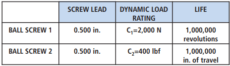
First, convert the life of the second screw to revolutions (by dividing it by screw lead):
L10(2) = 1,000,000/0.500
L10(2)= 2,000,000 revolutions.
Second, convert the dynamic load rating of the second screw to newtons:
C2 = 400 lbf x 4.45
C2= 1,780 N
Third, calculate the load rating of the second screw so life is reflected in 1,000,000 revolutions:
C2 = 1,780 N x (2,000,000/1,000,000) 1/3
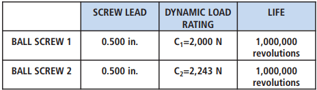
C2 = 2,243 N
The results show the load rating of the first screw is lower than that of the second one.
Let us assume that the first ball screw has been selected for an application. Then, consider the following application scenarios each with different objective:
Scenario 1. The application’s load requirement is 500 N. What fatigue life can be expected?
Expected fatigue life in scenario 1 is calculated as:
L10 = (2,000/500)3 x 1,000,000 = 64,000,000 revolutions.
This is an illustration of the fact that lighter loads significantly increase life.
Scenario 2. The same screw needs to be loaded with 5,000 N. Can the load rating be exceeded and what are the consequences with regard to life?
Expected fatigue life in scenario 2 is calculated as:
L10 = (2,000/5,000)3 x 1,000,000 = 64,000 revolutions.
Expected life is significantly lower than the basic rating life of 1,000,000 revolutions. This illustrates that any screw can be overloaded at the expense of life.
Scenario 3. A fatigue life of 100,000,000 revolutions needs to be achieved. How should the screw be loaded?
Load that can be attained in scenario 3 can be calculated as:
C = 2,000 x (1,000,000/100,000,000)1/3 = 431 N.
This shows that in order for the screw to last longer, its load should be decreased.
The above examples illustrate the L10 life-load relationship for rolling contact power screws.
Dynamic load factor
Fatigue is only one of the factors defining the useful life of a lead screw. The screw is also affected by wear, corrosion, contamination, strength of screw ends and nut attachments. Screws can also be subjected to a variety of dynamic elements inherent in the application such as load misalignment, and vibrations. Therefore, it is practical for a designer to apply some safety ratio when calculating screw life values.
Typically such safety ratio is provided by a dynamic load factor or coefficient, f = 1.5-2.0, included in the denominator of the load-life formula.
L10 = (C / P x f)3 , x 1,000,000 revolutions
where:
L10 – basic rating life,
C – dynamic load rating,
P – application load,
f – dynamic load factor.
Varying load
When the load varies during the working cycle, it is necessary to calculate the equivalent dynamic load Pe, a dynamic load acting on the screw axially and centrally, which if applied would have the same effect on the screw life as the combined actual loads.
The equivalent dynamic load is given by the following equation:
Pe = ( (1/L) x (P1 3 L1 + P2 3 L2+ … + Pn 3 Ln) 1/3
where
Pe – equivalent dynamic load,
P1, P2, … , Pn = varying loads,
L1, L2, … , Ln = distances, associated with varying loads respectively,
L = total distance traveled.
For example, let us consider an application with a total stroke of 12 inches and a load of 30 lbf acting over the first 8 inches of travel and 100 lbf acting over the remaining 4 inches of travel.
Equivalent dynamic load to be considered in this application’s life evaluation can be calculated as:
Pe = ((P1 3 L1 + P2 3 L2+ … + Pn 3 Ln)/L) 1/3 or,
Pe = ((303 x 8 + 1003 x 4) /12) 1/3 = 70.6 lbf
where,
L= 12 inches
P1 = 30lbf
L1 = 8 inches
P2 = 100 lbf
L2 = 4 inches
Static load rating
Another screw characteristic provided by the manufacturer is basic static load rating. While it does not affect life directly, it should also be carefully considered when selecting a ball or roller screw. The standard defines a basic static axial load rating of a ball screw, Co, as the static load acting axially and centrally, that corresponds to a total permanent deformation of ball and ball track at the most heavily stressed point of contact between the ball and the ball track of .0001 times ball diameter.
Summary
The fatigue life of a screw actuator is heavily influenced by the load being applied to its rolling components. Life can also be affected by wear, corrosion, contamination and other dynamic elements such as misalignment and vibrations. Predicting the life of these components can be done by applying the load/life equations to the specified screws, applying the proper safety ratios, analyzing the results and comparing the resulting performance when all the unit conversions have been made. Achieving expected or desired life is possible when carefully considering and calculating L10 values. Good designers do not accept “marketing” or advertised load values without qualifying them for a specific application.