 Ask an Engineer
Specifying electric rodless actuators: Ten tips for maximizing actuator life and system performance

Introduction
Electric rodless actuators have an inherent advantage over rod-style actuators for being able to support and carry loads. This reduces costs and design time by eliminating the need for other load-bearing and guiding elements. In contrast to rod-style actuators, a rodless actuator’s stroke lies completely within the length of its body, resulting in a smaller working footprint than rod-style actuators. In addition, electric rodless actuators can be either screw- or belt-driven, with each style having its own advantages depending on the application. However, sizing an electric rodless actuator involves more than merely calculating force and stroke. Following are the top 10 tips for achieving optimal performance, reliability and efficiency in applications using rodless-style actuators.
Tip 1: Calculate loads precisely
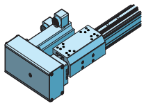
There are several loads and forces that need to be addressed in designing a rodless actuator for an application. In order for rodless actuators to perform as intended, it is important to match the motor, the selected screw or belt, the guide / bearing system, and any mechanical reduction device (gearbox, timing belt) to the anticipated loads in all three axes. Knowing the precise static and dynamic loads of the application and matching them to the peak and continuous load capabilities of the actuator will ensure that the application is both cost-effective and reliable (see Figure 1).
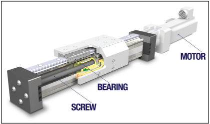
Figure 1: The motor, screw selection and carrier bearings all need to be appropriately sized for the forces anticipated in the application.
Tip 2: Don’t oversize electric actuators—calculate for electric, not fluid power (pneumatic or hydraulic)
When uncertainty creeps into the engineering analysis, there is a tendency to want to oversize an actuator’s capacity. This is a potentially harmful approach left over from fluid power applications, where oversizing was considered inexpensive insurance against not having enough power. It is common for engineers to build in a 2:1 safety factor on fluid power applications to compensate for imprecise knowledge of the loads, fluctuations in available air pressure, and the inability to fully control acceleration and deceleration motion at the end of the actuator’s stroke. Oversizing is also commonly done in anticipation of higher loads in the future due to production growth or application changes. But because electric actuators can require a larger upfront investment, oversizing may be a costly mistake. Avoid oversizing by properly matching the actuator’s capacity to the application’s parameters. Sizing programs, graphs and formulas available from actuator manufacturers make this task easier and more accurate than in the past (see figure 2).
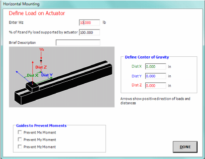
Figure 2: Sizing and Selection programs can help streamline actuator selection by guiding users through a step-by-step process.
Tip 3: Calculate moments
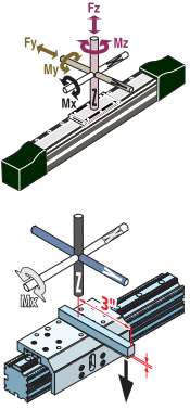
Rodless actuators carry the load, as opposed to rod-style actuators that push or pull the load. This difference makes it necessary to calculate the various moments (torques) that are being placed on the bearing system of actuator’s load-carrying platform, based on the position, size and weight of the load. For off-center or side loads, determine the distance from the center of mass of the load being carried to the center of the actuator’s load-carrying platform and calculate the resulting bending moment. For example, if the distance from the center of mass of the load to the center of the cylinder’s load-carrying device is 3 in., and the load is 30 lb., then: My (pitch moment in the Y axis) = 3 in. X 30 lb. = 90 in.-lb.
Similar moments should be calculated for the Mx axis (roll) and the Mz axis (yaw). The farther a load is from the center of the load-carrying device, the larger the resulting moment. Published bending moments are usually maximums and assume only one type of moment is being applied. In addition, dynamic bending moments are created by end-of-stroke acceleration or deceleration. Some applications contain compound moments that involve two or more of the moments described above. Each must be evaluated and calculated to determine whether the actuator can handle the combined moment forces.
Tip 4: Consider speed limits and inertia effects
In screw-drive actuators, be aware of critical speed limitations to prevent screw whip at higher speeds. When a screw reaches critical speed it begins to oscillate or “whip” as illustrated in figure 3 below. The critical speed limit depends on the screw length and diameter. As the stroke length increases, the distance between the screw support bearings increases, causing screw oscillation above a certain speed. This oscillation prematurely wears the support bearings and can result in vibration, noise and even catastrophic failure.
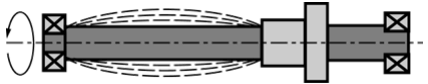
Figure 3: Screw whip in a rodless actuator
In belt-drive actuators, heavy loads may be difficult to start or stop because of the large inertia associated with speed and load. This inertia may produce excessive back-EMF in the drive motor when decelerating, which can adversely affect drive electronics, system stability and overall performance. It can also result in low-quality of positioning. Calculate the inertia in the application and then size the actuator and drive motor or gear arrangement to handle the inertial loads.
Tip 5: Factor in duty cycle
Duty cycle is defined as a ratio of operating time to resting time of an electric actuator, expressed as a percentage. An actuator that is moving for two seconds and stopped for two seconds has a duty cycle of 50 percent. Underestimating the impact of duty cycle on an actuator can lead to overheating, faster wear and premature component failure. Overestimating the impact of duty cycle can lead to higher initial costs due to oversizing. Overly conservative duty-cycle estimates often stem from an incomplete understanding of the application. This is another advantage of using sizing software programs as they can factor in duty cycles, move times, and velocities (see figure 4).
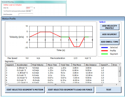
Figure 4: Tolomatic’s Electric Sizing and Selection Software can accommodate customized motion profile creation by factoring in duty cycles, move times, and velocities.
Tip 6: Carefully select mounting option
To avoid deflection in long-stroke rodless actuators, it is important to consider the number and location of support points to ensure mounting rigidity. The mounting surface needs to be straight. It is also important to consider the overall actuator “envelope” – the length and width of the actuator and motor. Failure to consider the total envelope may limit the size of motor that can be used, or it may require an alteration in the layout of the application. Be aware that the overall actuator length and actual working stroke length will be different due to the “dead length” needed to accommodate internal features.
Tip 7: The actuator’s drive system is more than a footprint
Rodless actuators may employ an inline or reverse-parallel (RP) motor mount/drive system. While a RP system offers a more compact envelope, it reduces the overall system efficiency due to addition of gear or belt reduction drives. Inline motor mounting offers the most efficient drive system and the highest dynamic performance. In some cases it is better to alter the application to make room for an inline motor drive than to specify a reverse-parallel drive where its performance characteristics may not be the best match.
Tip 8: Match life expectations with actuator capability
Screw or belt and carrier bearing life are greatly affected by load, bending moments, speed, duty cycle and environment. The useful life of any actuator depends on the durability of the components that perform most mechanical work or carry the most load. Lead screw drives are a typical example. Service (useful) life of a lead screw can be defined as the actual life achieved by a screw before it fails for any reason. Among possible reasons for its failure are fatigue, excessive wear, corrosion, contamination, insufficient structural strength or loss of any function required by the application. In general, life expectations are closely associated with dynamic loads. To achieve maximum life of an actuator, total load must be kept within the actuator’s design parameters as shown in figure 5 below.
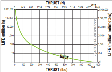
Figure 5: The chart above shows the maximum thrust in relation to life in millions of inches for a selected 5 turn per inch lead screw with a ball nut.
Tip 9: Verify accuracy requirements
Make certain that the precision of the actuator system meets or exceeds the application’s requirements for accuracy, backlash, straightness and flatness of linear motion. In screw-drive actuators, the selection of the screw is critical to accuracy, backlash and repeatability. To optimize straightness and flatness, choose carrier systems with precision profiled bearings. In belt-drive actuators, the accuracy is generally limited to ±.010”/ft. The mechanical system accuracy of a belt drive is affected by the fit between the belt teeth and sprocket (pulley) grooves. This fit is a function of manufacturing accuracy and proper belt tensioning, belt stretch, and system rigidity (particularly the amount of belt tooth deflection under load). Belt drive repeatability is generally under ±.001” and may also be affected by belt stretch over time.
Tip 10: Factor in environment
The environment in which the actuator will be operating can have a profound effect on performance, durability and maintenance. High temperatures can affect seals, lubrication, belts, bearings and motor life. Extremely low temperatures can also affect performance, lubrication and wear. Contamination with oil, water, aggressive cleaning procedures, or abrasive grit can destroy seals unless the actuator has an appropriate ingress protection (IP) rating. Since IP ratings address only static conditions when the actuator is not in motion, dynamic conditions (vibration, heat, cold, movement) also have to be considered.
Conclusion
Electric rodless actuators have many advantages over rod-style actuators in applications where heavy loads must be moved with accuracy and repeatability or where space is at a premium. However, when specifying electric rodless actuators, it is important to address the precise loads, inertias, moments, duty cycles and the operating environment of each application so that the actuator can be properly sized. Careful attention to these and other parameters in the design phase of a project will provide the best performance, highest efficiency and longest life in any given actuator application.