Ask an Engineer
Selecting the Optimal Screw Technology
Introduction
Many industrial linear motion systems employ screw mechanisms to achieve a desired linear motion. The intention of this technical document is to explain typical terminology used, evaluate the various screw technologies available, and provide a better understanding of the considerations involved in selecting the optimal screw technology for electro-mechanical actuation.
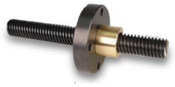
So, just what is a screw mechanism? A screw mechanism provides the means to produce linear motion by the rotation of either the screw or nut in an assembly. The screw is a cylindrical element with formed threads; the nut is a matching component to the screw. Each component is capable of rotating independently upon the other. By restraining one element linear motion occurs.
A lead screw is a generic designation that in its broadest sense may be applied to multiple screw mechanisms. There are three primary types of screw technologies used in linear actuators: Acme, ball and roller. The differences are in the design of the thread shape along with the design and operation of a matching nut. These differences within each technology and screw design will be detailed later in the following sections.
To provide an overall understanding of screw selection, it is first necessary to define common screw terminology and explain the different types of screws.
Screw Terminology
Accuracy – The ability of a system to achieve the targeted linear position.
Back-driving Force – The linear force or thrust required to rotate the screw or nut in a reverse fashion. For example, gravity in a vertical system may have the ability to back-drive a screw system creating torque and/or linear motion.
Backlash – The amount of free movement between a screw and a nut.
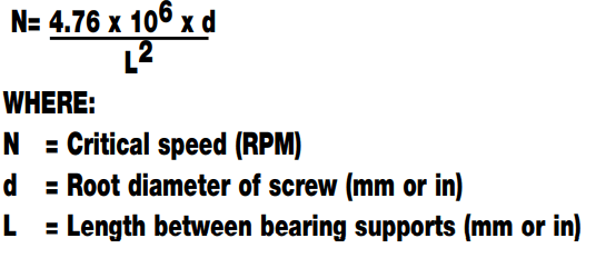
Critical Speed – The rotational velocity limit of the screw at which vibrations develop due to the natural harmonic frequency of the shaft. This is also commonly referred to as “screw whip” and is dependent upon the diameter and length of the screw between supports.
Duty Cycle – A percentage rating for an application that compares the amount of time running compared to the time at rest. An application that runs continuously would have a 100% duty cycle, where as an application that runs for 15 seconds and then rests for 45 seconds before completing another cycle would have a 25% duty cycle.
Dynamic Load Rating (DLR) – DLR is a bearing term that represents an applicable constant load (in direction and magnitude) where a ball bearing device will achieve 1,000,000 revolutions (rotations) of rated life or L10 life estimation at 90% reliability.
Grinding – A very precise manufacturing process which may be used for creating thread profiles on a screw shaft by the removal of material using an abrasive wheel.
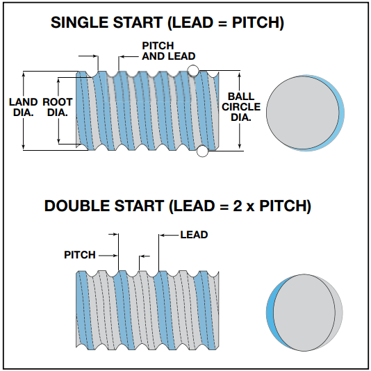
Lead –The linear distance of travel that occurs with one revolution of the screw or nut. Measured in units per revolution such as “mm/rev.”
Lead Accuracy – The possible variation in travel distance within a standard length of screw. Measured in units of variation over a given length in units such as “mm/meter.”
Pitch – The linear distance between threads. Pitch is not necessarily equal to the screw’s lead when a screw has multiple thread starts. Measured in units such as “mm.”
Pre-load – The amount of tension or pre-applied force set into a bearing system to remove backlash (play) in the mechanical assembly. This applies both to screw and nut combinations as well as linear bearing assemblies. For ball screw systems, this reduces axial and radial play and increases system stiffness and repeatability.
Repeatability – The ability of a system to achieve the same exact location in repeated attempts.
Rolling – A manufacturing process that forms thread profiles on a screw shaft through the use of high pressure forces in which rotating dies containing the desired thread profile are pressed against the blank shaft to displace material into the desired thread form.
Static Load Rating – The maximum load that may be applied to a stationary screw and nut system without damage occurring.
Turns – The number of revolutions required to travel a given distance.
Turns per Inch – Measured in units such as inch.
Screw Technologies
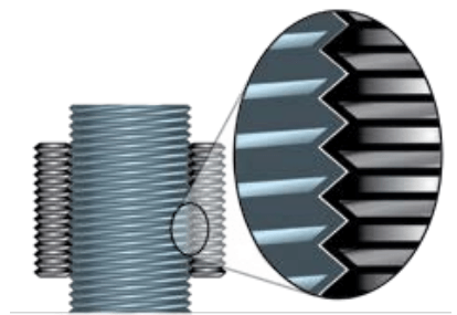
Acme Screws
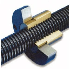
The Acme screw, first developed in 1895, utilizes a thread form having a trapezoidal tooth shape that is typically rolled into a steel shaft. The thread form itself is very strong and linear force is transmitted to a solid nut from the sliding surfaces on the flanks of the thread form.
The efficiency of a solid nut system is determined by the nut material and the lead, it can range from 20% to 40%, and is relatively low compared to other screw technologies. The low efficiency often prevents the load or external forces from back-driving the screw mechanism, which can be an advantage in some applications. However the disadvantage of the low system efficiency is increased motor torque input required in comparison to other screw technologies.
Common nut materials include self-lubricating plastics or resins and metals such as brass or bronze. Non-metallic nut materials generally achieve higher efficiencies due to their lower coefficients of friction and often do not require the use of lubrication. Metal nuts such as bronze are capable of higher working loads but may require lubrication which can be an issue in some operating environments due to contamination concerns.
The wear characteristics of the Acme nut is dependent upon the material, environment and application requirements. The amount and rate of wear can be difficult to predict due to the large number of application variables. To compensate for the negative effects of nut wear, some manufacturers construct Acme nuts using two halves that are biased to each other with a spring mechanism. Nuts of this design are commonly referred to as “zero-backlash.” It s important to note that these nuts may add friction to the system, and may increase nut wear.
Acme Screw Advantages:
- Low cost
- Quiet operation (when a plastic nut is used)
- May reduce or remove back driving
- Ideal for applications with:
- slow to medium speeds
- low positioning requirements
- low duty cycles
- low to medium force capacities
Acme Screw Limitations:
- Solid nut design may wear, increasing backlash, and affect positioning
- Lower efficiency ratings require higher input torque (larger motor or increased gear ratio)
- Unpredictable service life
- External factors such as environment can affect screw life
Ball Screws
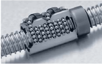
Ball screws utilize circular or ogival arch thread forms. The nut has a matched thread form allowing ball bearings that fit between the two grooves to transmit force and relative motion with high efficiencies, typically around 90% depending on screw diameter and screw lead.
The ball bearings are allowed to roll and recirculate through one or several circuits in the nut as rotation and linear motion occurs. There are various designs of ball screw nuts that differ in the number of ball circuits and how the ball recirculation path is controlled. The ball bearing path is a critical factor in determining the maximum speed of the mechanism. Alternative designs, such as internal paths or end returns, can offer advantages such as increased velocities or minimizing operating noise. However, most ball nut designs function similar in operation.
Ball screws are available in a wide variety of diameters, leads, and accuracies with both metric and imperial lead designs. A grade system is used to classify the lead accuracies of ball screws and is regulated by ISO-3408. Ball screws are commonly available in the 5 grades shown below.
| GRADE | LEAD ACCURACY |
| 1 | 6 µm / 300mm (~ 0.0002 in / ft) |
| 3 | 12 µm / 300mm (~ 0.0005 in / ft) |
| 5 | 23 µm / 300mm (~ 0.0010 in / ft) |
| 7 | 52 µm / 300mm (~ 0.0020 in / ft |
| 10 | 210 µm / 300mm (~ 0.0080 in / ft) |
The grade value of a ball screw can be used as a guideline for determining the lead accuracy of a specified system and is calculated in a cumulative fashion. These accuracy grades do not factor in backlash specifications. Typically grade 1 and 3 screws are ground with CNC equipment to achieve a high level of precision. Grinding, while precise, is also time consuming and a more costly manufacturing method. Rolling and whirling are two common methods of manufacturing screws with grades of 5, 7 and 10.
Low backlash performance in ball screws can be accomplished in a number of ways. A common design is to load each ball circuit with balls of a diameter that achieves the desired level of backlash. This method may also be used to achieve a preloaded system. Preloading can also be achieved by installing two nuts biased against one another and locked into position. Having two nuts on a single ball screw will not double the force capability of the system.
Ball Screw Advantages:
- Higher force capabilities compared to an Acme screw
- Longer life with predictable service life vs. Acme screw
- Increased efficiency (~90%)
- Typical backlash 0.127 mm (0.005 in); Low backlash 0.0025 mm (0.0001 in)
- Ideal for applications that require high duty cycles, medium to high force, and medium to high speeds
Ball Screw Limitations:
- May easily be back-driven depending on lead
- Higher initial cost vs. Acme screw
- Increased operational noise vs. Acme screw
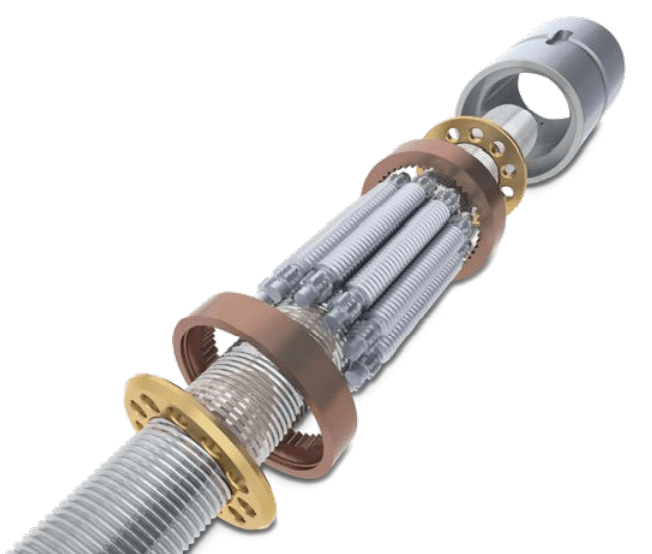
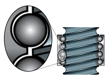
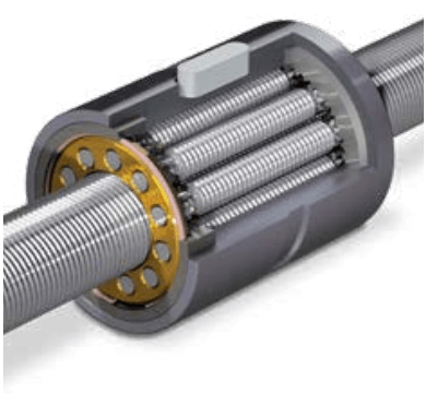
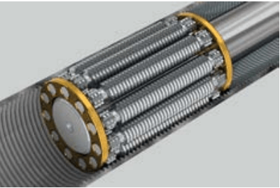
Planetary Roller Screw
A roller screw thread form is generally triangular in shape and transmits force through a matched set of multiple threaded rollers in the nut assembly. These rollers are allowed to rotate within the nut while contacting the thread form of the screw. The roller nut has a set number rollers that provide significantly more contact points with the screw in the same space compared to ball nuts, resulting in very high force transmission capabilities and a longer life compared to ball screws of a similar diameter.
Like ball screws, roller screws have a good efficiency rating because they are designed with rolling elements as compared to the sliding elements of Acme screws. Due to the increased areas of contact, the efficiency may be slightly lower than a ball screw, commonly around 85% depending on screw diameter and screw lead.
Roller screws, like ball screws, are produced within the ISO-3408 grade system so they share similar lead accuracy considerations. Roller screws are most commonly ground to provide continuous contact area, smooth motion, and high force outputs. Rolling and whirling are two alternate manufacturing methods for roller screws. These methods may be more cost effective but result in lower accuracy grade and reduced performance.
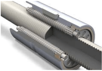
Standard Planetary Roller Screw
Standard roller screws are through hardened before precision grinding, resulting in a deep case hardness depth and high DLR. The deep surface hardness and high DLR give this design a large advantage in life over the inverted planetary roller screw design.
Inverted Planetary Roller Screw
Most inverted roller screws typically use processes other than grinding to economically create threads along the internally threaded nut. Because of this, the hardening process is performed after the internally threaded nut is machined. The required hardening process results in significantly more shallow case hardness depth and softer threads than standard planetary roller screws. This leads to much lower DLR (lower life) and more challenges with maintaining lubrication. Grinding an inverted roller screw is possible, however it leads to a much higher manufacturing cost.
Roller Screw Advantages:
- Very high force capabilities
- Extremely long life
- High speed and acceleration rates possible
- Low maintenance
- High efficiency
Roller Screw Limitations:
- Highest cost of three screw technologies
- In vertical applications, the screw can be back-driven or free fall with loss of motor torque
- Nut assembly has a larger outside diameter vs, ball screw
Screw Selection Considerations
Force
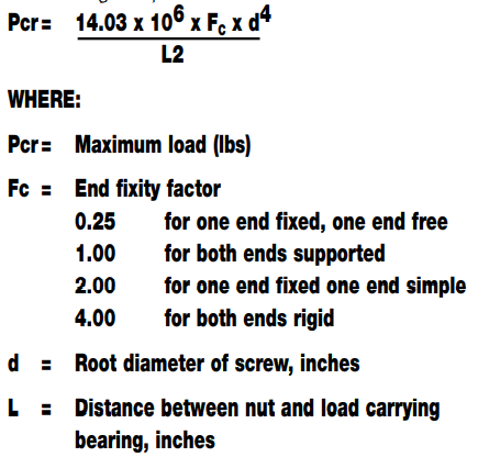
The axial force or thrust that is required by the application is one of the most important factors when selecting a screw technology. A higher force requirement will normally require an increase in the screw’s diameter because a screw is similar to a column that is subject to both compression and tension loading. During a compression load, it is undesirable for the screw to bow or deflect. During a tension load, it is important that the column can support the load without failing.
In metric units the theoretical formula to calculate the column strength in Newtons is:
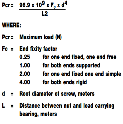
In U.S. standard units the theoretical formula to calculate the column strength in pounds is:
Another important factor is the nut design and nut material. For an Acme screw, the material selection of a composite resin or metal will have a significant impact on available force. For example, in a 25.4 mm (1-inch) metric Acme screw with a 3mm lead, the resin material nut may have an operating load rating of 2.75 kN (625 lbs), as compared to 5.50 kN (1,250 lbs) for a bronze nut. In a ball screw, the nut design and lead may affect the quantity and diameter of the ball bearings recirculating within the nut.
With an increase in number of balls inside the nut, the number of force supporting contact points increases, thus increasing the force capability. As a comparison, consider 50.8 mm (2-inch) ball screws, the first having a 5 mm (0.200 in) lead and the second having a 12 mm (0.500 in) lead. The first screw has a dynamic load rating of 4.33 kN (973 lbs) and is designed as a single start screw, two ball circuits with 40 balls in each circuit. The second screw has a dynamic load rating of 3.50 kN (786 lbs) and is designed as a double start screw, two ball circuits with 30 balls in each circuit. In these two screws, the number of balls in the nut is playing a significant role in determining the force capability.
The number of rollers in the roller nut have a similar effect, increasing its force capacity. The screw’s lead also affects the linear actuator system’s force capacity. To calculate the linear force output of a screw mechanism, the following formula can be used:
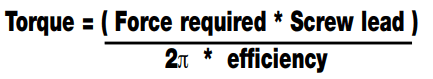
Example: An application requires 450 N (100 lbs) of continuous force using a 25.4 mm (1 in) Acme screw with a lead of 5 mm (0.2 in) and an efficiency of 40%. Using this formula, you would need an input torque of 0.30 Nm (8 lb in). If the lead was changed to 12 mm (0.5 inches), you would need an input torque of 2.15 Nm (20 lb in).
The above calculations assume a system with zero losses. There are additional forces that need to be accounted for such as bearing preloads, gravity, friction and breakaway torque into the equations above. The simplest and easiest way to account for all forces is to use a sizing tool such as Tolomatic’s sizing and selection software.
Speed
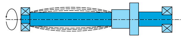
Speed is usually the second most important parameter to evaluate when selecting a screw. All screw mechanisms have a critical velocity — the rotational velocity limit of the screw after which vibrations develop due to the natural harmonic frequency of the shaft. This is also commonly referred to as “screw whip” and is dependent upon the diameter and length of the screw between supports. It is important to note that the critical velocity of a screw is not dependent upon the orientation (horizontal, vertical, etc).
A theoretical calculation for critical velocities applies when both ends of the screw are supported, however it is recommended that the maximum velocity is less than 80% of this calculation.
In metric units:
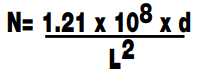
In U.S. standard units:
In ball nuts, bearings run along rolled or ground tracks between the screw and nut and through recirculation mechanisms. As the screw increases in speed, the ball velocities increase as well to a point where they become projectiles as they pass through the ball circuit. This complicated action, which needs to be controlled, can also limit speed.
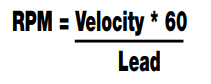
All lead screw designs maintain a direct ratio between the input rpm and output linear velocity, which is dependent upon the lead. In applications where high speeds are required, a larger lead can be specified that lowers the input rpm of the screw. Below is a formula to calculate the required RPM for screw mechanisms:
Accuracy and Repeatability
It is important to understand the difference between accuracy and repeatability, as these two terms are often used interchangeably. If misapplied or misunderstood, significant and unnecessary costs can result.
Accuracy is the ability to achieve the desired exact location within a tolerance level. To achieve accuracy, a screw must be selected with the lead accuracy required for the application.
Repeatability is the ability to achieve the same location upon multiple attempts. Many applications do not require a high degree of accuracy but will often require a high level of repeatability. It is possible for screw and actuator designs to be highly repeatable without being highly accurate.
Ball or roller screws, because they do not wear like Acme nuts, maintain a higher level of repeatability over their life. Backlash, the next area of discussion, is also an important consideration for bi-directional repeatability.
Backlash
Backlash is the amount of linear movement between the screw and nut without rotation of the mechanism. This can be a critical factor for applications that require stiffness or accuracy and repeatability from both directions of travel. Example: An application requires travel in a positive direction to an absolute position of 254 mm (10.000 in). When direction is reversed, the actuator and screw mechanism are commanded to move to an absolute position of 127 mm (5.000 in) by the motion controller. If the actuator, for example, returns to 127.254 mm (5.010 in) there would be 0.254 mm (0.010 in) backlash.
External forces that are acting on the actuator can also play a role in determining if backlash will be a factor for your application. In a vertical application, gravity will normally keep a downward or negative force on the actuator, thus eliminating the possibility of seeing the effects of backlash. In some applications, an external force may be acting against the linear actuator, such as products on a conveyor belt or a pneumatic cylinder, removing the backlash effect.
System Feedback Resolution
Resolution is normally related to the motion controller, motor and feedback devices in a linear actuator system. Preload, break-away torque and the torsional twist of long screws may also play an important factor if moving small increments, such as <0.0254 mm (<0.001 in). It is important to let the vendor of the components know your expected accuracy and repeatability requirements with the addition of your smallest incremental move. The lead of the screw also has a major effect in the system resolution. Selecting a finer screw lead will provide a system with higher resolution. This is important to note because your system solution may require a lower resolution feedback device or lower cost motor and drive if a higher resolution screw is installed. It is important to keep in mind that the screw’s lead will also affect the maximum linear speed and linear force output.
As an example, consider a lead screw that has a 12 mm (0.5 in) lead as compared to a 5 mm (0.2 in) lead. Looking at the linear travel per degree of motor rotation, there is a considerable difference that may result in a more economical motor and drive solution.
12 mm lead — 0.0033 mm/deg 5 mm lead — 0.014mm/deg
(0.5 in lead — 0.0014 in/deg 0.2 in lead — 0.0005 in/deg)
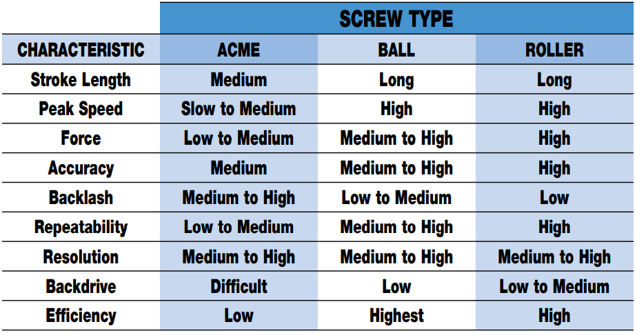
Screw Technology Comparison
The following chart shows the overall comparisons of using the types of screw technologies in electromechanical actuators and how it affects the performance characteristics of the actuator. It is important to understand the requirements of the application when selecting a screw and nut for an application in a linear motion system.
Summary
Sizing Considerations
It is important to understand the requirements of the application when selecting a screw and nut for an application in a linear motion system.
First, determine the answers to the following questions:
Load:
- Are there multiple components?
- What are the masses?
- Where are the centers of gravity?
Orientation:
- How will the actuator be positioned?
Move Profile:
- What is the total length of travel?
- What is the fastest move profile?
- What is the duty cycle or frequency of the move profile?
- How accurate does the move need to be?
- How repeatable does the move need to be?
- Will backlash be an issue?
These decisions will not only influence the choice of screw technology, but also the total system performance.
Acme screw applications
The contact surfaces of the Acme screw system are solid surfaces sliding against each other and therefore offer quiet operation if composite nuts are used compared to recirculating elements of a ball screw mechanism. Therefore, applications that require near silent operation will benefit from an Acme screw and nut selection.
Acme screw and nut systems are also the most economical, but there is a trade off associated with a lower cost. Acme screws are the least efficient of the screw technologies. They have a comparatively high rate of wear and as a result can experience the highest amount of backlash. Acme systems are a good choice for low duty cycle applications where cost is an important factor and accuracy or repeatability is of a lesser concern.
Since most Acme screws will not back drive, Acme systems can also be a good choice in applications where back-driving is undesired, such as a vertical installation. Applications with slow speed and low positioning requirements are also good choices for Acme screw/nut systems.
Ball screw applications
Ball screw systems are available in a wide variety of diameter and lead combinations and are graded for their lead accuracy. While they are higher in cost than Acme screw systems, they offer higher force capacity, longer life, are available with higher accuracy, and consistent backlash.
Ball screw systems are good for applications that require high loads and tight positioning. The industry offers a wide degree of flexibility in screw diameter and lead combinations. Low friction, relatively long life, and consistent performance are attributes of ball screw systems. However, the increased efficiency can make them more apt to back driven. When used in vertical applications, the use of a brake or other mechanism may be required to assure appropriate functionality and safety. Ball screw systems are widely used and are the workhorse of linear motion systems.
Roller screw applications
Rollers screws have an increased contact surface area between the rollers and screw shaft threads. They provide higher load carrying and force capabilities than ball screws of a similar diameter. The roller screw manufacturing process is very precise and labor intensive, so their relative costs are typically considerably higher than ball screws. Roller screw technology is well suited for applications where extremely high forces or extended life are required. Standard planetary roller screws have a deeper case hardening process than inverted roller screw designs offering longer life. If an application requires high force or long life, roller screw technology can be a good choice.