Ask an Engineer
Go Beyond Motor Curves for Accurate Integrated Actuator Sizing
By John Fenske on February 18, 2026
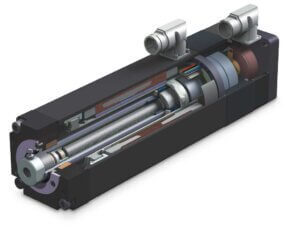
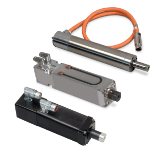
Today’s automation experts are increasingly specifying servo linear actuators to achieve high-performance motion because they offer dynamic responsiveness and precision. The convenience and simplicity of a motor and actuator in a single unit is also attractive. However, when assessing these actuators, many engineers rely on continuous force/speed curves derived from motor data, which can lead to an overestimation of actuator performance.
Continuous force/speed curves for the motor offer a high-level estimation, but they often fail to account for the mechanical and thermal losses inherent in a complete servo linear actuator system. Relying too heavily on these simplified charts can lead to under-sizing, resulting in performance issues and costly delays. To ensure a design meets expectations, it is critical to evaluate servo linear actuator performance within the context of full system operation.
The Limitations of Standard Performance Curves
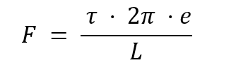
The continuous force/speed curves for some servo linear actuators are typically generated by converting the servo motor’s continuous rotational torque/RPM curve into linear units using the screw’s lead and efficiency values. This is often calculated using the following formula:
Where:
- 𝐹 is output force
- 𝜏 is input torque
- 𝑒 is screw efficiency
- 𝐿 is screw lead
The resulting curve represents the theoretical maximum performance of the actuator based on the motor’s specifications, but it ignores real-world factors such as:
- Back-and-forth motion.
- System acceleration and deceleration.
- Heat generated by the screw.
Accounting for mechanical and thermal losses provides a more realistic expectation of integrated actuator capability. A thermally limited force/speed performance curve provides a much more accurate picture of what the actuator can handle over long-term production.

A comparison between standard (red), physically limited (orange) and thermally limited (green) force/speed curves.
Thermal and Mechanical Considerations
Screws are not 100% efficient; they generate heat that contributes to the system’s total thermal load. Because screws generally have lower thermal thresholds than the motor’s stator windings or magnetic core, they effectively lower the system’s overall thermal limit.
This limitation is particularly significant for roller screws because of their lower efficiency and thermal limits compared to ball screws. Operating within these lower limits is essential to protect the hardware and ensure the estimated L10 life does not decrease.
Calculating L10 Life for Reliability
The L10 life is a calculated lifespan, after which 10% of bearings are expected to fail due to fatigue based on the characteristics of the actuator and its application. This calculation uses the dynamic load rating (DLR), the equivalent load and the screw lead.
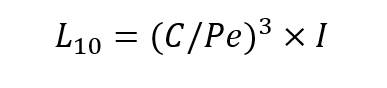
Where:
- L10 is the L10 life
- C is the DLR in pound-feet (lbf) or (N)
- Pe is the equivalent load (lbf) or (N)
- I is the screw lead in inches per revolution (in/rev) or millimeters per revolution (mm/rev)
While constant loads are straightforward, varying loads require calculating an equivalent dynamic load to reflect the combined effect of different load increments throughout the working cycle. For calculating L10 for a dynamic load, the formula remains the same. However, the equivalent dynamic load must be calculated with the following:
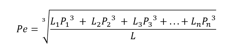
Where:
- Pn is each different load increment (lbs) or (N)
- Ln is each increment of the stroke at its associated load in (in) or (mm)
- L is the total distance traveled per cycle, which is the sum of all Ln values
Advanced Sizing Tools
Keep in mind that thermally limited force/speed curves are visual representations. They cannot account for every unique application variable in all real-life performance cases. For deeper insight, engineers should pair these curves with sizing software.
For instance, Tolomatic’s SizeIt software goes beyond standard motor data to evaluate critical pass/fail criteria such as:
- Buckling load and critical speed.
- Acceleration limitations.
- RMS rpm and peak torque.
- System and screw thermal limits.
By defining system requirements early and using comprehensive sizing tools, you can balance cost and performance while ensuring long-term reliability.
Read our full white paper on servo linear actuator performance:
Learn More