 Ask an Engineer
Mounting Your Motor to an Electric Actuator
Electric Actuator Motor Mounts
Introduction
Selecting and installing a 3rd party motor on an electric actuator is a popular option for many industrial customers. There are many different types of motors (servo, stepper, induction) available on the market and each selection can affect the mechanical design (mounting and coupling) of the actuator. Customers choose a certain type of motor for many different reasons ranging from ease of use, brand, availability, performance, package and size, among other considerations. This paper will explore the advantages of both the inline and the reverse parallel motor mounting designs for electric actuators to help inform the reader and avoid common mounting mistakes.
|
|
|
|
Inline Motor Mount |
“Reverse Parallel” Motor Mount |
2. Design Advantages
2.1 Inline Motor Mount Advantages
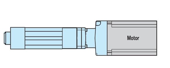
Inline Configuration (LMI)
With an inline motor mount, the motor mounts directly inline with the driveshaft of the actuator. Fewer components are needed in this design to couple the motor to the actuator. This direct coupling allows the actuator to perform more accurately with the reduced backlash compared to the belt and pulley system of a reverse parallel motor kit. In addition, an inline motor mount takes up less space in the width and height of the actuator solution but will make the overall length much longer. The inline motor mount also limits the number of rear pivot mounting options such as a rear clevis.
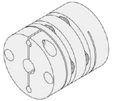
There is a coupler inside of an inline motor mount that links the motor to the actuator’s driveshaft. There are several types of couplers commonly used: spider, servo or rigid (fixed). Deciding which type to use typically depends on the application requirements.

Spider Coupler: A standard spider coupler utilizes two coupler halves with jaws that engage a rubber “spider” material between the two halves. This design is easy to manufacture, economical, and allows for some alignment correction to occur between the motor’s shaft and the actuator’s driveshaft to compensate for any misalignment. Spider couplers are commonly available in both aluminum and steel designs. Manufacturers of spider couplers typically have guidelines as to whether aluminum or steel should be used based on application torque requirements. In general, aluminum is used for lower torque applications and steel is used for higher torque applications.
Servo Couplers: Another popular design is the “Servo Style” coupler. This design tries to provide advantages of both rigid and spider coupler styles. This design consists of an aluminum coupler material with mid sections machined to allow for some flex to occur in the absence of a rubber spider material. By leaving the rubber spider material out of the component’s design, backlash is theoretically less compared to a spider type. A servo coupler is typically more expensive than a spider coupler due to its mechanical complexity.
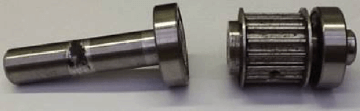
Failed actuator driveshaft due to alignment/flex issues
Fixed Couplers:The “fixed” coupler is typically used where application parameters call for zero backlash or extremely high torque applications. This is not the most common or popular type of coupler because it is the most difficult to implement correctly. A “fixed” design requires that there be no misalignment between the actuator and motor shaft. If the two shafts are out of alignment, it could side load either shaft. During normal operation, this misalignment could result in shaft fatigue and damage to the motor/actuator bearing system. This could result in permanent damage. Care must be taken when using a fixed coupler to ensure system alignment. A servo or spider coupler is typically recommended to help with any misalignment.
2.2 Reverse Parallel (RP) Mount Advantages
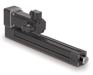
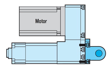
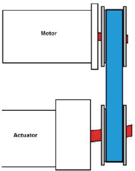
Reverse Parallel Configuration (RP)
With a reverse parallel motor mount design, the motor is mounted parallel to the actuator and coupled to the actuator drive shaft through belts/pulleys or gears. This type of motor mounting allows for both rear trunnion and rear clevis pivot mounts, increasing mounting flexibility.
The belt material used in the reverse parallel design will have some amount of compliance, which can result in slightly higher amounts of backlash and lower repeatability when compared to an inline design. Backlash will affect the overall precision of the system.
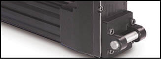
Clevis Mount (PCD)
In the RP mounting configuration, actuator manufacturers typically offer 1:1, 2:1, and 3:1 belt reduction ratios. In some cases, a higher ratio of 5:1 can be achieved when using a gear set. In a belt/pulley configuration with a 2:1 ratio, the motor pulley would be twice as small as the actuator pulley allowing the motor to spin twice as fast as the actuator’s driveshaft. Through this mechanical advantage, twice as much torque is provided to the actuator’s driveshaft. These ratios can be overlooked by consumers causing additional cost expenditures. For example, if the motor used in an application cannot provide the torque required, a common practice is to purchase a gearbox to increase the torque input to the actuator. Gearboxes are usually required to achieve a large torque ratio. However; a change in the pulley ratio can often negate the need for a gearbox. A gearbox can significantly increase the cost of the actuation solution, whereas a change from a 1:1 belt/pulley ratio inside the actuator’s mount to a 2:1 ratio is often available as an option at minimal cost.
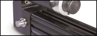
Trunnion Mount (TRN)
3. Motor Mounting
3.1 Inline Motor Mount
With so many different motor designs to choose from, mounting a pulley on the motor’s shaft can require special couplers. Some common coupling techniques include collar clamps, trantorque, or set screw designs.
A collar clamp is a popular design due to the ease of installation. A trantorque is more complex and requires a working knowledge of how they are constructed to avoid installation challenges.
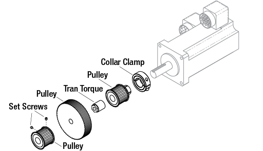
Common Motor Pulley Attachments
A trantorque consists of a cylinder shape body with a hole through the center and a hex head provided on one end. When installing a trantorque bushing, the motor’s shaft is slid into the bushing and the motor pulley is slid over the bushing. To keep the motor shaft from spinning, it needs to be held in place while turning the hex pattern with a wrench to allow the trantorque bushing to grab onto the motor’s shaft and tighten itself to the motor pulley. A torque spec from the manufacturer should be referenced during installation.
A set screw pulley design is another method of coupling a pulley. The set screw concept works best with either a keystock on the motor shaft or when there is a flat on the shaft for the set screw to engage.
Video examples of how to mount an inline motor can be found by following the links:
Spider coupler design: https://www.youtube.com/watch?v=42CHDVeAxUQ
Fixed coupler design: https://www.youtube.com/watch?v=pmTnspIgj-I
Torque to apply for coupler connection
| Required Torque | ||
| Thread Size | in-lbs | N-m |
| #5-40 | 20 | 2.260 |
| #6-32 | 25 | 2.825 |
| #8-32 | 46 | 5.198 |
| #10-24 | 67 | 7.571 |
| 5/16-18 | 135 | 15.255 |
| M3 | 13 | 1.469 |
| M4 | 40 | 4.520 |
| M5 | 67 | 7.571 |
| M6 | 135 | 15.255 |
Typical torque specifications for various coupler types
3.2 Mounting a Motor in RP Orientation
A video of how to mount a reverse parallel motor can be found by following the link below:
Reverse parallel design: https://www.youtube.com/watch?v=CIjljaeooMA
Mounting a motor on a reverse parallel motor mount which utilizes a belt and pulley design can require more attention compared to the simplicity of the inline design. While tensioning the belt, attention must be paid to the process to avoid over or under tensioning the belt. Belts that are under-tensioned will cause the belt’s teeth to cog (skip teeth). Belts that are over-tensioned will cause the belt to side load the motor shaft and the actuator’s driveshaft.
Example of the shafts fatiguing from applying excess belt tension
Note: A gear set design inside the reverse parallel housing is much like mounting an inline motor. It is simply bolted on and a few components are tightened to their correct torque.
Many actuator manufacturers have created their own tools to set the belt tension correctly and consistently from one actuator and motor combination to the next. However, consumers typically do not have access to these custom tools.
Refer to the instructions below to properly tension a belt-driven actuator with a reverse parallel motor mount. The procedure reflects a collar clamp style pulley. This tensioning method may slightly vary between a trantorque or set screw pulley design and a high torque (HT) standard torque (ST) actuator design.
3.2 Instructions for Reverse Parallel (RP) Installation
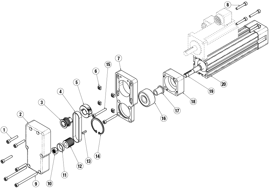
Example exploded view of reverse parallel configuration
-
- Take the cover from the reverse parallel (RP) housing (2) off the motor mount (7). Position the motor pulley (3) and its collar clamp (5) so it engages the belt (3) keep the belt loosely tensioned by mounting the motor to the mount without the RP cover installed. The motor fasteners (8) and nuts (6) can be used to loosely hold the motor to the mount (7). Do not put tension on the belt with the RP cover off or damage to the leadscrew (19) and/or RP mount could occur due to the RP cover not being installed to provide the mount and leadscrew with additional strength.
- Once the motor is located on the mount, move the motor pulley to the correct location on the motor shaft so the belt is centered on both pulleys. The motor pulley must have the motor shaft through at least 50% of the pulley to be considered a properly mounted pulley. Tighten the collar clamp fastener to the torque spec provided by the actuator manufacturer. If a trantorque design is being used, consult the trantorque manufacturer for the required torque spec. This situation would apply for a set screw pulley design as well. The motor will likely have to be removed from the mount to tighten the pulley on the motor shaft to its correct location and correct torque requirement.
- With the pulley tightened on the motor shaft, reinstall the motor onto the mount. Tighten the four motor flange fasteners until they tighten with the motor face engaging on the mount. Then, back the fasteners off 1 or 2 turns so that the motor face is close to the mounting surface but still moves freely up and down.
- With the belt cover off, slip the belt on to the pulleys. Check again to make sure that the belt is engaging with the pulleys correctly and that it is not rubbing on anything inside the motor mount.
- Hold the motor in place so that the belt does not come off of the pulleys. If needed, tighten one of the motor flange fasteners to hold the motor in place. At this point, no tension should be applied to the belt. This is meant to simply hold the motor and un-tensioned belt in place on the pulleys.
- Install the RP cover on to the mount.
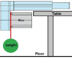
- After the RP cover is installed, apply weight to the belt. To do this, hang the correct amount of weight from the motor’s flange. Tolomatic uses the smallest shaft diameter (motor or actuator) as a guideline to determine the amount of total weight that should be applied to the motor, in order to tension the belt. The table below displays these total weight values. The amount of weight being applied to the unit needs to include the weight of the motor. This “total” weight concept is a good way to approach this mounting method when working in the field.For example, if the smallest shaft diameter (motor or actuator) is 0.5″ (12.7 mm), a total of 31 lbs (14.074 kg) of weight would need to be applied to a reverse parallel belt material. This means if the motor weighs 8 lbs (3.632 kg), an additional 23 lbs (23 lbs + 8 lbs = 31 lbs) (10.442 kg + 3.632 = 14.074 kg) of weight would need to be hung from the motor to create the total 31 lbs (14.074 kg) of pull force on the belt. Keep the weight on the motor as close to the mounting surface as possible. After this weight is attached to the motor, loosen the one tightened motor fastener so the motor moves downward from the pull force of the motor’s weight and additional weight that has been applied.
- Once the motor has moved as far as it can go with the total amount of weight applied (in this case 31 lbs), tighten all the motor flange fasteners.By doing this, the 31 lbs (14.074 kg) total of tensioning force applied to the RP belt material, will have ensured that the RP belt is centered on the pulleys and that the belt is not rubbing on other components.
Weight to apply for correct RP tensioning
| SMALLEST SHAFT DIAMETER (Motor or Actuator) |
TOTAL WEIGHT TO APPLY |
||
| inch | mm | lb | kg |
| 0.18 to 0.259 | 4.572 to 6.579 | 13.0 | 5.902 |
| 0.260 to 0.499 | 6.604 to 12.675 | 22.0 | 9.988 |
| 0.500 to 0.625 | 12.7 to 15.875 | 31.0 | 14.074 |
| 0.625 and larger | 15.875 and larger | 40.0 | 18.160 |
4. Conclusion
Several motor mount styles are available in actuator solutions. Depending on the application, torque, and mounting requirements, a reverse parallel or inline mounting configuration may be recommended. Care should be taken when sizing an actuator to ensure that the optimal mounting, design style, and belt reduction ratio is selected. Additionally, special attention should be taken during the motor mounting procedure to ensure alignment and proper belt tension is applied to optimize the overall life of the actuator.
Contact your Tolomatic application engineering team for any questions regarding electric actuator motor mounting.