 Ask an Engineer
Guide to Third Party Motor Integration
Tolomatic
Best Practices for Matching Integrated Actuators or Motors to Various Manufacturer’s Drive
Introduction
The most important aspect of an automation project is a cost-effective, functional result. This seems reasonable to most machine designers, engineers, and other stakeholders. Early decisions in the design and implementation process can have a significant impact on an overall project timeline, cost, and success. Yet, no matter how much planning and attention to detail goes into designing an automated system, problems may arise where one or more axis of motion do not operate as expected. That triggers a process of debugging and troubleshooting. This document is a resource that can be used for automation projects during design and development, execution, or troubleshooting in the event of unforeseen challenges.
Topics covered:
- Process for defining axes of motion, sizing calculations and use of sizing software
- Feedback selection and protocols
- Considerations for matching integrated actuators or motors with third party servo drives
- Cable type and length considerations
- Environmental protection and Ingress ratings
 Important Note:
 A. Process for defining axes of motion, sizing calculations and use of sizing software
In this section we will review factors to be considered using the example of a Tolomatic IMA (Integrated servo motor actuator) that will be used with a servo drive from a third party manufacturer.
Early on in the design phase of automation projects, it is not uncommon to have the initial motion and loading factors only partially defined. The definition of these factors often comes into more focus as components are selected.
Having a process to follow when defining axes of motion, along with engineering tools like sizing calculations or sizing software programs can be beneficial. The following steps are recommended to ensure potential risks and consequences are being considered in sizing an integrated actuator:
- Gather motion / load and environmental requirements for the application
- Validate the best and worst case application scenarios
- Calculate loading conditions or find a good sizing software
- Compare the results based upon performance, size and cost
- Select the appropriate features and options
- Verify solutions with an applications engineer
Step 1: Gather motion / load and environmental requirements for the application
The first step is to gather the known requirements to make the application work and hold up in the environment. Common considerations include:
- Motion & Load Variables
- Stroke (distance), load (mass), force, speed (time), duty cycle (dwell times, cycles/minute)
- Environmental Variables
- Ambient temperatures, contamination (i.e., dust, debris, chemicals, weld slag/spatter, etc…)
- Ingress protection
- Splashing, spraying, raining
For example, in a rapid assembly application, parameters may be clearly defined for travel distance, time per cycle, number of cycles and tooling load. More difficult calculations might be the external forces to overcome, or duration of a move when this force is being applied. Defining these details can be challenging. However, the selection of an actuator based upon complete and accurate variables in the beginning will result in a more reliable, cost effective and functional solution in the end.
Step 2: Validate the best and worst case application scenarios
Once all of the requirements are compiled, the next step is to assess all the different motion scenarios for each requirement. For example, there may be multiple travel scenarios to plan for:
a) The travel to move far enough to clear tooling,
b) The travel required to engage the part and press it into place.
Each of these separate travel requirements may have separate process time requirements while still needing to achieve the total cycle time requirement. These moves may also have unique loads or forces. In this document we refer to the maximum loading condition as “peak” and the average of all the moves as “continuous.” This is generally how servo motor manufacturers will talk about torque requirements for rotary applications. It is also important to note that “continuous” takes into account not moving whether loaded or unloaded. This is why it’s very important to be as accurate as possible with defining all aspects of a linear motion application.


Step 3: Calculate loading conditions or find a good sizing software
Defining your loads can oftentimes be straightforward. Others can be more complex with multiple points of mechanical advantage or external dynamics that must be calculated. An example of this is a robotic Resistance Spot Welding (RSW) assembly as shown.

Figure 1: Robotic resistance spot welding (RSW) example
When doing complex calculations on pivoting applications — or when using linkage assemblies – it is important to take into account operational inefficiencies, load distribution, and mechanical angles of advantage or disadvantage in these assemblies.
It is possible to have a situation where all the parameters are rigidly fixed, but this is rarely the case. There are plenty of complex equations to work through to determine all of the static and dynamic influences on an actuator in an application like this. You can grab your favorite pencil and notepad or spreadsheet to do the math like calculating the maximum axial force (thrust):
F = (2π / I)* e*m*em* (TACC LOAD + TEXT + TGR) (lbf)
OR
To simplify the process, there are powerful engineering software packages like Tolomatic’s SizeIt that manage all of the calculations for you. This can drastically cut the time to size up solutions and minimizes the chance for errors when using complex engineering formulas; including back checking for speed torque curves with multiple speeds and loads/forces.
With Tolomatic’s sizing software, the user starts by entering the parameters collected in Step 1 and motion scenarios from Step 2, as described above. The software will prompt you through the selection and data input sections as follows:
- In the “Motion Profiler” the software asks for the full cycle. This should be the total motion cycle and include the dwell times where applicable.
- In the “Product Selector” it is important to select the products that the software should evaluate. In the example shown, the IMA (Integrated Motor Actuator) will be selected.
- The screw technologies of either ball screw or roller screw can be selected based on desired life and cost, which will be covered later in this guide.
- When a motor is going to be evaluated and selected, in the “Motor Specifications” the winding voltage selection can also be made. Incoming power to the system might influence on the final selection, a topic also covered later in this guide.

Step 4: Compare the results based upon performance, size and cost
Upon reaching the results page, a list of results based on the inputs will be shown. In Tolomatic’s SizeIt software all of the passing actuator results are listed by default. From this list, the user is allowed to select the best fit based on their defined criteria. Reviewing actuator performance, such as estimated life and force or speed margins, is typically the primary focus. There are times when price may take precedent, so results can also be sorted by price. If no results are available, or if a desirable solution is not in the list of passing results, the “Why failed” list can be reviewed. If changes to the inputs can be made — or data was incorrectly entered — the user can simply go back, make adjustments where applicable and check again for passing results. This is where having powerful sizing software is very useful compared to manual calculations.
Step 5: Select the appropriate features and options
A sizing software tool like this has benefits in addition to simply running calculations. In the “options” portion of the software, users have all the available options to select at their fingertips. Need the ability to pivot? Trunnion or clevis mounts can be selected. Need special protections? Select the appropriate lubrication or ingress protection options. The Tolomatic sizing software asks for connector and feedback selections as well. The sizing program provides reports with data summaries and also provides links to select models.
Step 6: Verify solutions with an applications engineer
Once the sizing exercise is complete, one final step is recommended: contact an applications engineer for a second opinion. At Tolomatic, there are trained engineers ready to help confirm the selection made and adjust if there are any modifications required (standard or special). They can also assist with the next step of getting a quote.

B. Feedback selection and protocols
1) Feedback Selection
When integrating an actuator into a third party control system, there can be a significant number of factors that go into making the final actuator feedback selection. Single turn resolutions, accuracy, temperature, shock, and vibration should all be considered. Resolution and accuracy are often a consideration when the application demands precise, smooth, and small motions. Temperature, shock, and vibration should be considered when the actuator is working in harsh environments. Some examples of harsh environments could include wood processing, oil and gas, and mobile applications. The following table can help with the selection of the correct feedback technology based on what feedback specification is critical in the application.

Table 1: Feedback technologies comparison
Another question to ask when making the final feedback selection: Does the application need to know or remember actuator position after power is removed? The benefit of a multi-turn absolute encoder versus other feedback types is that in the event of a power down situation the actuator will always remember its position when powered back up. This is true even when the device is moved while powered down. This eliminates the need to re-home the actuator. Listed below are some common multi-turn technologies on the market, and how they rank when considering shock, vibration, noise, and life.

Table 2: Performance characteristics of multi turn technologies
Feedback devices continue to get smarter as we move into the future. When making a final decision, it’s important to consider whether the application requires smart feedback (on-board memory). Consider the following benefits to determine whether smart feedback is required for the application:
- Actuator / Motor File Information stored on the feedback device (plug and play functionality)
- Actuator / Motor Fault History
- Actuator / Motor Live Temperature Data
- Actuator / Motor Diagnostic Information (Faults, Counter, Speed, Etc….)
- SIL2 Machine Safety

2) Feedback Protocols
In the case of absolute encoders, one of the biggest challenges in integrating with some servo drive manufacturers is that they have developed their products to accept only certain protocol types or, in some cases with larger manufacturers, they have developed special feedback devices and communication protocols. In the following table we list some common feedback protocols utilized by major servo drive manufacturers in the automation world today. Some of the feedback protocols mentioned below allow for single cable technology, where power and feedback wires are combined. The goal is for the integrated actuator manufacturer to make their motors look like the third party servo motors built by the various major manufacturers listed below. Some actuator manufacturers have worked closely with motor/drive companies to further simplify the communication and feedback integration. With the use of a smart encoder, specific programs can be loaded into the feedback device to support simple, and in some cases plug-n-play integration. Furthermore, using some of these feedback devices also allows the user to utilize diagnostic data that is being monitored by the servo drive.
Feedback Protocols Summary

Table 3: Feedback protocols of some of the major manufacturers
 Note:
Note:C. Considerations for matching integrated actuators or motors with third party servo drives
When matching a drive to an integrated motor actuator, there are a few important considerations that will help ensure a successful application. Some of the considerations that will be discussed in this section are:
- Encoder types
- Speed and force: peak versus continuous
- Current: peak and continuous
- Voltage calculations
- Drive sizing and selection
- Operating modes; which will help define drive sizing and selection
1) Encoder types
Not only is it important to ensure you have the proper feedback device for the application as discussed above, but also one that is compatible with the intended drive manufacturer for the application.
2) Speed and force: peak versus continuous
When sizing an actuator for a particular application, it is important to size the peak separately from continuous ratings. To determine the peak ratings of an actuator, there are 2 main considerations:
a) What is the fastest travel needed?
b) What is the maximum force needed to push at any moment in time throughout the application?
Peak ratings for speed and force
Determining the maximum speed required of the actuator is relatively straightforward and applies to the motor in the same way as the load for the mechanical portion of the system. This is calculated with the maximum required speed of the application, the pitch of the screw, and any ratios due to the application’s tooling.
Similarly, the maximum force required from the actuator can be calculated with any mechanical advantages and inefficiencies. Some examples of mechanical advantages might be if the actuator is operating a lever or “scissor-style” pinch mechanism.

Figure 2: This resistance spot welding gun is an example of a “pinch style” mechanism
For a pinch style mechanism (shown in Figure 2), the arm lengths act as a gearing ratio. The ratio of this weld gun is Y/X, so the force delivered at the tips is

Likewise the tip speed would be calculated as such

It’s also important to determine if the maximum speed and maximum force of the application are occurring simultaneously. If this is the case, another check should be done: Can the actuator provide this force at this speed? Can the motor? This is determined by looking at the peak speed torque curve which is a fundamental property of all brushless servo motors and servo motor actuators. When using Tolomatic’s online sizing tool, this check happens automatically for both the motor and actuator in a fully integrated assembly.

Continuous ratings for speed and force
Separately, A sizing check should also be done on continuous duty cycle applications. Simplistically, continuous duty cycle is the time-average amount of work the actuator is being asked to perform. This is what contributes to how much heat is being generated by the actuator and drive. Typically this calculation is done in a software program specifically designed for sizing integrated actuators like Tolomatic’s SizeIt. It is done by separating out each motion segment individually.

We’ve discussed how to size for operation at peak forces and how to calculate continuous forces based on peak force operation. However, there is also a limit to how long peak operation can be sustained. This is a function of operation above continuous and the thermal time constant of the integrated motor actuator. In the stamping example described above, the actuator is heating up when the work is being done (in this case, a holding force). When the actuator retracts, it is cooling down. The overall system temperature will stabilize after a number of hours operating in this manner.
For any applications, it is important to consider the peak time on of the system. This is how long a system can operate in the peak zone before it requires down-time to alleviate potential issues (thermal limits, etc….)

3) Current: peak and continuous
Below is a detailed calculation example for a specific IMA actuator to define current requirements. Once again, data properly placed into a manufacturer’s sizing software will do much of this calculation work.
The following example illustrates the calculation process to determine current requirements for drive electronics:


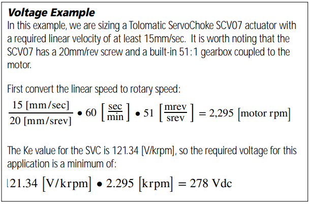
4) Voltage Requirements
Tolomatic’s integrated motors are specially designed to match well with commercially available drives. Tolomatic will commonly refer to integrated actuator capabilities as low voltage (230 VAC) and high voltage (460 VAC). This will correspond to the input voltage for the drive that is best suited for the motor winding.
It is important to make sure that when pairing servo motors and drives that these components are not only rated for the application requirements but that the servo motors and drives are properly rated to run together. Depending on the combination, the servo drive can provide more voltage to the motor winding than the insulation is rated to handle. In these instances you can see a rapid breakdown or failure of the motor. Another possible scenario would be that the drive cannot provide enough voltage to the motor which would limit its output speed.
In situations like this, you can calculate the voltage required by the motor and compare this to the drive output voltage to check if there may be a compatibility or performance issue. Below is a simple example of how to check voltage compatibility.

5) Drive sizing and selection
As an increasingly global economy emerges, manufacturers are having to consider national and regional differences in how their equipment will be installed and used. First and foremost are the power requirements of automation equipment. North America uses 110, 240, and 480 AC voltages operating at 60Hz to power equipment. Outside of North America there may be power sources of 208, 330, 470 AC and more with voltages operating at 50Hz. When selecting a drive, make sure the drive is rated to accept the input voltage for the geography where it will be installed. Confirming proper input voltage will be important when using the bus voltage requirements (discussed in the previous section) to select the appropriate drive. It is also common for servo drives to accept a range of input voltages. Many drives can run on 110 VAC up to 240 VAC, 330 VAC to 480 VAC or even 600 VAC and up. Keep in mind that not all drives will be able to accommodate single and three-phase input power.
After voltage and current requirements have been determined, it’s time to determine what size drive is required. When doing so, it is important to make sure the drive electronics are properly matched. Be sure that the drive has the proper power handling capabilities to be able to provide enough current for the peak thrust requirements.
In the case where the actuator’s current requirements are significantly less than the drive’s capabilities, the motor may be difficult to tune and properly control. As a general rule of thumb, the actuator’s current draw in a given application should be between 10% and 80% of the drive’s current rating. If over 80%, there may not be enough overhead. If there are any errors in sizing, it may be necessary to step up to the next larger drive size/chassis. Likewise, if operating below 10% of the drive’s capabilities, issues may result with the resolution of the current being supplied to the motor. This will create challenges delivering precise force (torque) due to the aforementioned current resolution at lower power. How a drive is sized also has a direct impact on system design and cost. The more power is required, the larger the package size and the higher the cost.

6) Operating modes
After choosing proper power requirements and feedback compatibility the drive will work properly. One of the last steps is to make sure the drive has the correct operating modes available for the application. Some operating modes are position, torque control and speed control. Linear actuators will most commonly run in positioning mode. This is because the actuator will be asked to move to a series of predefined positions, which is exactly what positioning modes are designed for.
D. Cable type and length considerations
Power and feedback cables are often overlooked when designing control systems. There are some important specifications and considerations that determine final cable selections for an application.
When designing and implementing systems with integrated actuators or motors and various manufacturer’s drives, the best practice is to utilize the cables that have been tested and verified by the specific servo drive manufacturer that will be used. If this is not possible, the following factors should be considered:
1. Consider the drive manufacturer’s recommendation on the proper cable dressing for servo drive. (For example, flying leads, ring terminals, exposed shielding, drive specific connectors.)

2. Consider the drive manufacturer’s recommendation for the proper grounding and shielding type for the servo drive

3. Make sure that all differential signals used for the specified feedback device have individually shielded twisted pairs

4. Important cable markings to consider
- Appropriate agency listing (UL, CE, etc….)
- Temperature rating
- Wire gage size for application current levels
- Voltage rating

5. a) Integrated actuator manufacturer’s recommendation for maximum cable length (with and without extension cables) OR
5. b) Motor and drive manufacturer’s recommendation for feedback and power cable maximum cable length specifications
It is important to pay attention to maximum cable length specifications on both the feedback and power cables. The following issues can result when cable runs are too long:
- Lengthy power cable runs can produce partial discharge inception voltages onto the servo motor, causing the motor insulation system to break down, and eventually reduce the life of the actuator.
- Lengthy feedback cable runs can reduce signal voltage levels, causing random feedback faults due to weak signals.
E. Environmental protection and ingress ratings
Whether the motion system is going to be mounted into a medical, industrial, or mobile application, protecting components from the environment can be one of the most difficult challenges to address. With a wide variety of variables to account for, this task can seem daunting. There are several ingress points to evaluate for motion systems. We will take a closer look at each of these:
1) Motors/Actuators 2) Electrical Connections 3) Drives
Summary of IP Ratings

Figure 3: Summary of IP Ratings
Let’s take a closer look at the various ingress points to evaluate for motion systems.
1) Integrated motor actuators and motors
Since some components of a motion system are dynamic, they are the most challenging elements to protect from moisture and contamination. Most commonly the IP rating system will be used to classify how well will be protected from the elements. These ratings apply only to static assemblies or when dynamic assemblies (like linear actuators) are in a static state. Extra care should be taken when putting linear actuators and motors into challenging environments, as there is still the potential to induce ingress into these components even when properly rated. For example actuators that are rated as IP69K are designed to resist ingress of high pressure water (1450 PSI) and high temperature water (80C) in a static state. However, if the actuator is in motion while subjected to these types of conditions, the likelihood of ingress is high. The same would be true in dry environments where dust and particulates are present.
Note: Consult drive manufacturer for specifics on enclosure ventilation.2) Electrical Connections
Electrical connections are more straightforward to address since they are static. However, attention to their ratings must also be reconciled with the application environment that will surround them. There are also several different styles of connectors within each sealing category that may also be specific to an application in addition to a sealing requirement.

NEMA motor characteristics

Table 4: Summary of NEMA motor IP characteristic

3) Drives
Drives may have NEMA, IP or both types of ratings depending on the design and manufacturer’s preference. Often drives will be mounted within environmentally appropriate electrical panels. When sizing drives that will be mounted into an enclosure, care must be taken to ensure there is proper ventilation to keep the electronics from overheating.
F. Summary
There are many elements to matching an integrated motor actuator to a servo drive. The tools and resources provided by both drive manufacturers and actuator manufacturers, like Tolomatic, are making the process simpler all the time. While determining electrical and mechanical requirements can be done through manual calculations, consulting a design engineer and using the expert tools provided by manufacturers like Tolomatic can eliminate errors and expedite the design process for applications.
Photo credits:
- Gerd Altmann from Pixabay
- bridgesward from Pixabay
- ThisIsEngineering from Pexels
- 3D Animation Production Company from Pixabay