 Ask an Engineer
Electric actuator technology comparison: Integrated and traditional designs
Introduction
In the fast-paced industrial automation industry, machine design engineers build systems that meet evolving and demanding requirements. Their choices for linear motion include a wide selection of electric actuator technologies, both integrated and traditional, to help achieve designs that are reliable and efficient. Each technology offers performance advantages depending on the application type and requirements. There are several factors to consider when evaluating integrated and traditional actuators; knowing how to assess the differences and what to compare will help engineers meet their spec requirements (Figure 1).
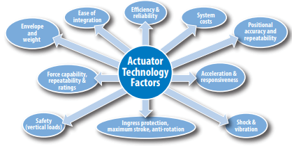
Figure 1: Actuator technology factors
Traditional actuators are defined as a screw assembly driven by an external motor attached to the actuator by a coupler, belt or gearbox. The screw assembly is supported by an angular contact ball bearing set and rotated by the external motor. The nut assembly coupled to the thrust rod provides anti-rotation (typically internal), creating linear motion.

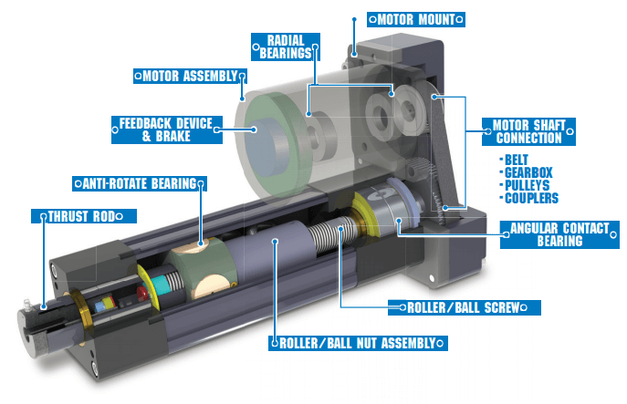
Figure 2: Traditional actuator assembly
Integrated actuators are defined as a screw assembly rigidly coupled to and driven by an internal hollow-core servo motor. The screw assembly and nut assembly travel within the hollow-core rotor of the internal servo motor. A set of angular contact ball bearings supports the screw assembly and servo motor rotor assembly. Anti-rotation is applied (typically external) to the thrust rod and nut assembly, creating linear motion.
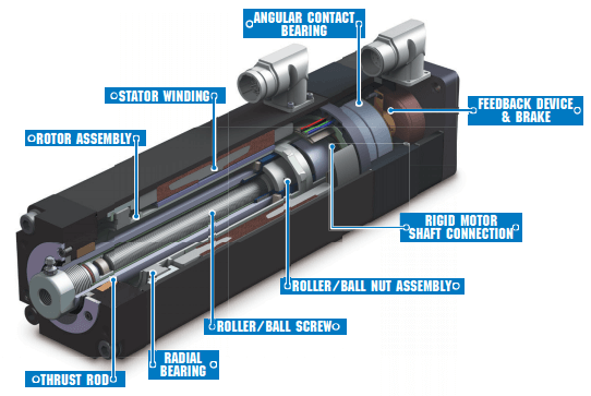
Figure 3: Integrated actuator assembly
Ease of integration
As speed-to-market pressures increase, an important factor to consider when building and commissioning new machines is how easily each component integrates into the machine design.
A traditional actuator (mechanical actuator and external servo motor with feedback device) is typically sourced with the servo drive and motion controller. An integrated actuator combines the mechanical actuator and servo motor into one motion module that must be integrated with servo drive and motion controller.
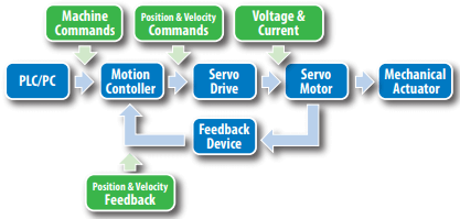
Figure 4: Closed-loop, single-axis motion control system for an electric actuator
Traditional actuators
A third-party servo motor is mounted to a traditional actuator. This motor is usually manufactured by the same manufacturer as the servo drive, thus facilitating easy integration between motor, drive and controller with compatible connectors, feedback devices and cables. Actuator suppliers can provide or recommend the correct motor-mounting provisions, such as belts, pulleys, hardware and the correct motor-mounting plates. Motor mounting, usually done at the customer site, requires accurate shaft engagement, motor alignment and belt tension to avoid issues such as side loading the motor shaft. This motor-mounting process adds time to the overall actuator integration and commissioning processes.
Integrated actuators
Integrated actuators utilize connectors and feedback devices engineered to match those of leading servo motor manufacturers on the market. Machine builders can use standard servo drive and motor cable offerings from the drive manufacturer to facilitate easy electrical and mechanical integration with the servo drive. Integrated actuators save designers commissioning time by eliminating the motor-mounting procedure and additional components. Unlike a traditional actuator, an integrated actuator typically requires additional time to manually enter the integrated actuator’s motor parameters into the servo drive and perform tuning for the actuator system. Most servo drives allow for third-party motor integration, and once completed a motor file is created allowing for much quicker integration time with repeat machine builds. An advantage of integrated actuators is their flexibility to maintain mechanical form, fit and function for multiple control system designs by changing the feedback device and connector options to match each control system brand without requiring any change to the mechanical design of the machine. Traditional actuators would require two different servo motor brands, which could drive requirements for multiple mechanical designs to accommodate the variety of servo motor dimensions from brand to brand.
Size considerations – envelope and weight
Envelope
Traditional actuators, which require an external motor mount, typically offer both motor fold-back (also known as parallel motor mount) and inline motor-mount options. When comparing actuator overall length, both a traditional parallel mount actuator (25-75mm) and traditional inline mount actuator (200-250mm) will be longer when compared to a similar performance integrated actuator. Some of the length variance between integrated and traditional inline actuators is dependent on motor and feedback options selected. For height comparison, integrated actuators are slightly more compact than a traditional actuator with inline motor mount (typically 2-3mm smaller) and significantly more compact than a parallel motor-mount configuration. The parallel configuration extends the height of the actuator by as much as 430-460 mm. Depending on the motor selection, the width of the traditional solution could be similar to an integrated solution or slightly larger.

Table 1: Dimensional comparison of Tolomatic actuator technologies (RSA24 vs IMA33)
Weight
Weight comparisons are often essential for applications such as robot-carried, mobile and similar applications where the actuator is part of the moving mass. The weight of traditional actuators varies, depending on the selected motor and additional components such as a gearbox. All three actuator configurations can offer similar weights, again dependent on the motor selected and the additional motor-mounting components. In certain applications, an integrated actuator may be an advantage. The integrated actuator’s compact design places the center of gravity along the center axis of the actuator and closer to the mounting face. This allows the integrated actuator to facilitate more efficient movement, a characteristic especially useful for robot end-of-arm applications. If weight is a key application factor, compare all three actuator configurations with the motor sized for the application requirements to ensure the optimal configuration.
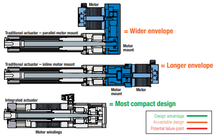
Figure 5: Integrated actuator designs are the most compact option
System costs
It’s possible that both technologies meet a system’s design and performance specifications. If that’s the case, then cost is an important factor to consider. The purchase cost of a traditional actuator is often less than an integrated actuator, but when the traditional actuator factors in the servo motor cost, the actuator system cost typically becomes slightly higher. Integrated actuators have competitive pricing and eliminate motor mount time, often making them the most economical option.
Platform considerations – ingress protection, maximum stroke, anti-rotation
Ingress protection
Traditional actuators with externally mounted motors require an increased number of components, resulting in an increased number of mechanical joints that require sealing to prevent water from entering the actuator. A comparison of two similar-performance actuators finds that a traditional actuator had 10 seals/gaskets and 34 external bolts. The similar integrated actuator had six seals/gaskets and 16 external bolts. With reduced mechanical joints and fasteners, integrated actuators have fewer potential ingress points compared to traditional actuators, making integrated actuators the technology of choice for demanding applications subject to high-pressure wash-down or for outdoor applications where environmental conditions (rain, snow, etc.) result in water presence around the actuator.
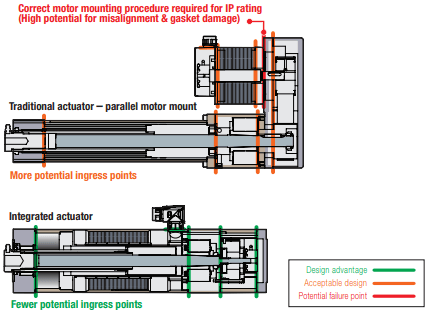
Figure 6: With reduced mechanical joints and fasteners, integrated actuators have fewer potential ingress points
Maximum stroke
Both traditional and integrated actuator designs utilize a fixed/free screw support system. One important mechanical difference between the two actuator designs is the roller/ball nut assembly support mechanism. In a traditional actuator, the nut is supported at the point where it attaches to the thrust rod. This support mechanism traverses the actuator through the entire stroke length. With the nut assembly support mechanism, typical traditional actuators can achieve stroke lengths up to 1.5m. An integrated actuator, however, utilizes a hollow-core rotor assembly, which cannot provide continuous nut assembly support throughout the entire stroke. This results in a limited stroke length of 600mm for some models, because the fixed-location nut assembly support mechanism (known as thrust rod front bushing) does not travel throughout the stroke.
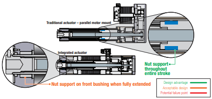
Figure 7: Traditional actuators provide improved nut assembly support allowing for longer stroke lengths
Anti-rotation
The nut assembly support mechanism for traditional actuators serves a second purpose by providing anti-rotation, which is necessary to achieve linear motion. The nut assembly support mechanism contacts (slides) the actuator housing extrusion, allowing for anti-rotation throughout the stroke length of the actuator. Integrated actuators typically utilize the machine design or tooling design to provide the anti-rotation function external to the actuator. If anti-rotation is required as part of the actuator functionality, external guide rods or special thrust rod designs such as a hex shape or spline are options. Both splined and hex rod designs provide internal anti-rotation, but sealing challenges make these designs more challenging (but achievable) to utilize in applications requiring IP65 ingress protection ratings.
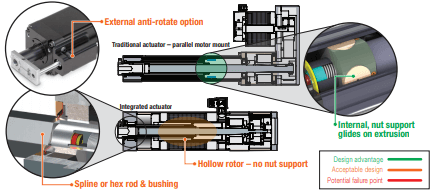
Figure 8: Traditional actuators provide standard internal anti-rotation while maintaining IP ratings
Efficiency and reliability
Efficiency and reliability differences between integrated and traditional actuators are driven by the number of torque transmission and rotating components in each system. Misalignment and the resulting side loading also negatively impact system efficiencies. In an integrated design, only two support bearings (radial bearing and angular contact bearing) are required, and alignment is tightly controlled within the assembly. Traditional actuator platforms have significantly increased component counts and require three to four bearings: two radial bearings in the motor and a set of screw support (angular contact) bearings. Additionally, a traditional actuator system utilizes a belt and pulley assembly in parallel motor-mount designs or a coupler in the inline configuration. These additional torque transmission components are subject to wear, misalignment and potential side loading, which can further negatively impact efficiency through increased friction and lower overall potential system reliability. Integrated actuator designs have fewer components, which eliminates additional bearings and motor connection components that can potentially wear and fail, making integrated designs more reliable. Integrating the motor assembly of traditional actuators requires accurate alignment and belt tensioning. Over-tensioning the belt results in a side load to the motor shaft, decreasing efficiency and increasing the chance of premature motor bearing failure. Additionally, if a gearbox is utilized, the gearbox efficiency will reduce the overall system efficiency. In summary, integrated actuators reduce friction and operate at a higher efficiency level due to their reduced component count.
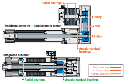
Figure 9: Integrated actuators have the highest efficiency and reliability with reduced component count
Positional accuracy and repeatability
While the same screw design (ball or roller) can be used in both integrated and traditional actuators, the connection between the servo motor and the screw is essential to minimize backlash at this location, which directly impacts position accuracy and bi-directional repeatability. Integrated actuators utilize a rigid connection between the rotor and screw shaft, resulting in a coupling style that does not introduce backlash into the system. A traditional actuator relies on a belt/pulley mechanism, motor coupler or a gearbox to attach the motor’s shaft (rotor) to the actuator’s screw assembly. These connection options typically result in ~0.1 to ~0.5 degrees of backlash, which negatively impacts position accuracy and bi-directional repeatability of the actuator.
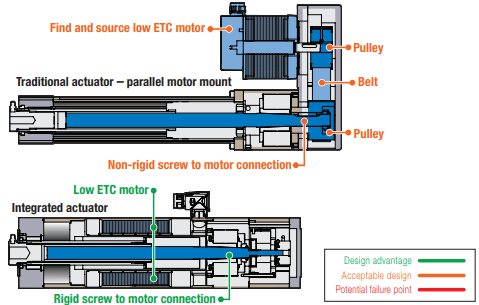
Figure 10: Integrated actuator’s rigid motor connection provides superior positional accuracy and bi-directional repeatability
Force capability, repeatability and ratings
Force capability
Due to their construction, traditional actuator designs allow for the use of large-diameter ball and roller screws. Integrated actuator designs limit the size of the screw assembly, as it is constrained to travel inside the hollow-core rotor of the servo motor. This allows traditional actuators currently on the market to achieve peak force ratings upwards of 445kN (or 100k lbf). Integrated actuators currently offered on the market are capable of achieving forces around 54kN (or 12k lbf). A technical reason limiting the commercial feasibility is the flexibility of traditional actuators to accept almost any servo motor/gearbox/belt and pulley combination to generate the torques required to achieve the high force ranges. Design engineers can source and match servo motor/gearbox combinations to achieve the speeds and forces required for their applications, further increasing the application range flexibility of traditional actuator technology.
Repeatability
Servo motor design directly impacts the force repeatability of the actuator. A motor with a skewed winding reduces torque ripple and cogging, which will provide superior force repeatability independent of rotor position and thrust rod position. Motors with skewed windings can be specially sourced for traditional actuators. Some integrated actuators offer skewed motor windings as a standard offering.
Ratings
An important distinction to consider between manufacturers is whether the actuator’s continuous ratings have taken into account the temperature rise limits of all critical components inside the system. These critical components are typically the servo motor insulation system, feedback device, connectors, bearings, screw assembly and grease. Continuous ratings for the actuator system established on the complete thermal system will ensure the longest and most reliable actuator. Power losses from the servo motor and brake assemblies, and frictional losses from the screw assembly and bearings, are the main contributors for generating heat into the actuator system. A traditional actuator can run at higher duty cycles and higher peak force ranges for extended times because the power losses from the servo motor and brake assemblies are separated from the frictional losses of the screw assembly and angular contact bearings, reducing the temperature rise of both the motor and screw assemblies. With more surface area, this helps to increase natural convection heat transfer. This characteristic makes traditional actuators the recommended technology for applications in elevated ambient temperatures. An integrated actuator, with its compact design, positions the servo motor winding in close proximity to the screw assembly, which in turn puts the winding power losses and frictional losses in close proximity. This type of design will likely increase the temperature rise of all the critical system components when running high duty cycle or high peak force applications.
An advantage of integrated solutions is that the ratings factor in the limitations of all components in the system, whereas traditional actuators are often deployed with motor/gearbox combinations that have capabilities that far exceed the thermal capabilities of the mechanical actuator components. Mechanical actuator limitations affect control systems design and should be factored into the control settings along with the servo motor and drive.
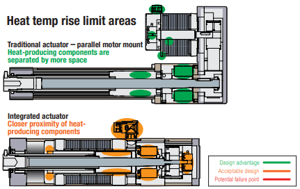
Figure 11: Traditional actuators provide better performance in high duty cycle and peak force applications due to more favorable heat dissipation characteristics
Acceleration and responsiveness
An actuator’s acceleration capability and responsiveness are dependent on the servo motor’s electrical and mechanical time constants, as well as the stiffness of the components to couple the servo motor rotor to the screw assembly. The lower the mechanical time constant (MTC) and the electrical time constant (ETC) of a servo motor design, the faster the rotor will respond to voltage and current inputs into the winding. Low ETC and MTC servo motors can be sourced for both traditional and integrated motor designs. The equations below illustrate how both of the parameters can be calculated from standard motor performance specifications.
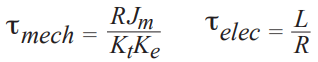
Figure 12: Mechanical and electrical time constant equations
Additionally, the inertia and stiffness of the components selected to couple the servo motor rotor to the screw assembly will determine the actuator system’s resonant frequency response.
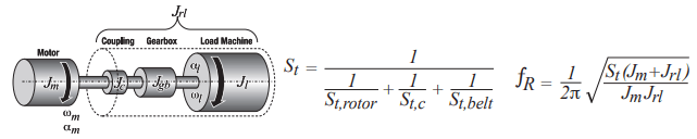
Figure 13: Equivalent motor load model (reflected & motor inertia) – Total torsional stiffness equation – System resonant frequency equation
Traditional actuators utilize couplers, belts, pulleys and gearboxes, all of which influence inertia and compliance (stiffness reduction) between the servo motor and screw assembly. This in turn affects the resonant frequency of the actuator system. Integrated actuators utilize a rigid connection between the rotor and screw assembly to create a very stiff torque transmission system. This allows for increased system resonant frequency, allowing integrated actuators to achieve higher acceleration rates and increased responsiveness.
Figure 14: The rigid connection in an integrated actuator creates a stiff torque transmission system resulting in increased acceleration rates and responsiveness
Shock and vibration
The distance between the actuator mounting face and the center of gravity affect the actuator’s sensitivity to shock and vibrations (see Figure 15). Both actuators utilize a front-face mounting feature. Shocks and vibrations occurring at the mounting surface are transferred through the actuator assemblies. The further the center of gravity is from the mounting surface, the larger the stress on the mounting fasteners and the higher level of accelerations at the end of the actuator. The integrated actuator has a center of gravity much closer to the mounting surface. A given shock or vibration of magnitude a at the mounting surface will be transmitted and magnified through an integrated actuator increasing by approximately 2.5x at the farthest point from the mounting surface. In a traditional actuator, with its increased length, the same vibration input is magnified by approximately 4x. As shocks and vibrations are magnified, they often result in high acceleration rates at the end of the actuator, which can not only affect the mechanical actuator but also other components like connectors, cables, feedback devices, as well as belts/pulleys/couplers. Integrated actuators offer a very compact design that maintains a center of gravity close to their mounting surface, making them a preferred choice for applications where shocks and vibrations are present.
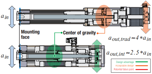
Figure 15: Integrated actuators provide a center of gravity closer to the mounting face, resulting in higher tolerance to shock and vibration loads
Safety considerations (vertical loads)
Actuator technology selection plays a significant role in safety for vertical applications where control of the actuator position and load (tooling) in power loss or component failure scenarios is critical for product or operator safety. Both traditional and integrated actuator assemblies utilize holding brakes to hold the motor rotor in power loss scenarios. Traditional actuator designs utilize an external motor with a belt or coupler system between the brake and screw assembly. With a catastrophic failure of a belt or coupler, the result would be a free moving or uncontrolled actuator rod and tooling mass. In this scenario, the brake would be unable to stop or control the actuator load from falling due to the failed coupling system. An integrated actuator design is ideal for vertical applications with safety concerns. Its rigid connection eliminates the potential failure points between the brake and the actuator screw assembly. This design ensures that in a power loss scenario the brake will have engagement with the actuator screw and stop the screw assembly from rotating.
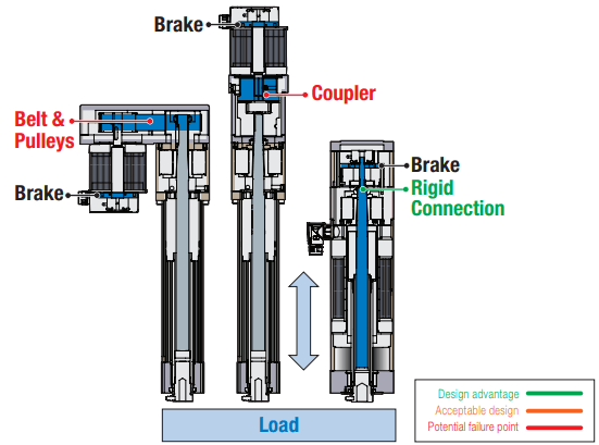
Figure 16: Integrated actuators provide a rigid connection between the brake and screw assembly to ensure safe operation in vertical applications
Summary
Due to the wide range of applications, industries and requirements, it is important for machine designers to evaluate both integrated and traditional actuators (advantages and tradeoffs) against their requirements.
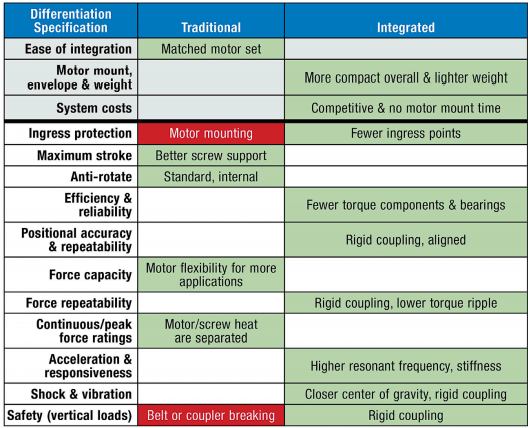
Table 2: Summary of technical attributes of traditional and integrated actuator technologies