Rules of actuator and guide alignment in linear motion systems
Introduction
Are you experiencing any of the following from your linear motion system?:
- Inconsistent linear motion results
- Expecations for the predicted life of the linear bearing system not being met
- Premature wear or failure of the actuator system
- Erratic motion such as speedvariation or wobbling during the cycle
If so, then you may be in a “bind.”
Many automated machines rely upon linear guidence components, such as profiled rail, round rail or otherrolling or sliding bearing structures, to guide and support the moving elements are driven by some type of linear actuator device. This paper will discuss ways to enhance overall system performance by optimizing the “alignment” of the linear actuator.
Actuators and Guides
While there are numerous ways to impart motion to a guided machine member some of the most common fall into two categories. the first category is rod-style actuators or pneumatic, or electric such as a lead screw or ball screw.

Figure 1: Electric rod-style screw actuator and a pneumatic rod-style actuator
The second is rodless actuators. These, too, may be either fluid powered or electric via a lead screw, ball screw, belt or linear motor. Both styles of actuators find applications in guided systems however, each has subtle differences in how it is beast employed to maximize performance and life.
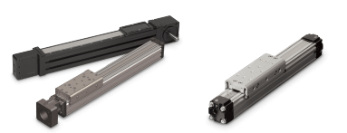
Figure 2: Rodless electric timing belt and electric screw actuators (left); Pneumatic rodless actuators (right)
The guide elements themselves, whether profiled rail, round rail or the other rolling or sliding systems, must be properly sized and selected during the design phase and installed following the manufacturer’s recomendations, paying particular attention to the process of alignment. Doing so assures that the performance of the selected guidence system is maximized for the particular application.
Importance of compliance members
Rod-style actuators, characterized by the piston rod or actuator rod extending and retracting with each cycle, typically offer numerous mounting options. Mounting options such as drilled and tapped holes in the device, mounting feet, spherical rod joints, alignment couplers, clevises or trunions are commonly offered by most suppliers of rod-style actuators. When employed with a guided mechanism, care must be exercised to assure each subsystem, actuator and guide assembly is capable of unimpeded, smooth motion. Systems that attempt to ridgly couple the drive elements try to move in separate planes with one or both of the systems loaded beyond its capability. (See figure 3.)

Figure 3: A rod-style actuator is mounted without compliance members and as a result no motion is possible.
A rod-sty;e actuator in such a system is best employed with some compliance member between the drive member (actuator) and the driven (guide system). For example, a spherical rod end mounted to the actuator rod allows the mounting point to swivel about the spherical joint. This type of connection at the guide is best used in conjunction with a trunion of clevis at the opposite end of the actuator where it attaches to the machinery frame element. ( See figure 4.)
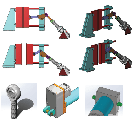
Figure 4: (Top) Compliance members help to prevent binding that would occur in an actuatorwithout compliance members driving a guided load. Compliance members on rod-style actuators include a spherical rod end at the front of the actuator and a clevis or trunionmount placed at the rear of the actuator.
Such a mounting scheme allows compliance in the connection without adding undue stress to either the drive (actuator) or the driven (guide system).
Rodless style actuators, charactorized by their stroke being contained within their overall length, may also contain a fuide system built into the actuator. Rodless actuators, wen used in conjunction with a separaate guide system, as mentioned above, will also need to include a compliant member in the connection between the drive and driven members. Most actuator suppliers offer a variety of mounts intended for this type of installation, such as floating brakets. (See figure 5 and 6.)

Figure 5: The illustration above shows a rodless actuator mounted to a rail system with nocompliance members present.
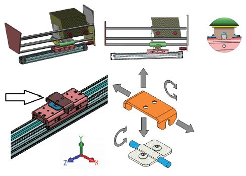
Figure 6: (Top) Rodless actuator shown with a floating mount as a compliance member; (Left) Arrow pointing to floating mount on rodless actuator; (Right) This type of mount allows motion along the Y and X axis plus rotation along the X and Z axis with the pin and slot joint.
Rodless actuators that include a guide system can perform the task of guiding and supporting the equipment while taking the place of a separate guide system. This feature can be particularly useful and many times saves the machinery builder time and money in the process. Rodless actuators with integrall guides can be built into the machinery in combinations to meet a wide variety of motion needs. Multi-axis configurations such as X-Y or X-Y-Z along with gantry configurations are all possible with the proper sizing. In the installation of rodless actuators with the integral guides, alignment is equally important.
Parallelism and Perpendicularity of Joined Elements
A rodless actuator with an integral guide used in a single-axis configuration only needs to meet positioning expectations. The alignment process is straight forward as the actuator works sigularly bringing its load into position without any external guidance. Examples are, work-point-to-work-point or alignment-to-fixturing on the equipment.
Alignment of rodless actuators need to work together. Therefore, mounting must consider conditions of parallelism and perpendicularity of all joined devices for optimal performance and maximum service life.
Parallelism of joined elements
There are three variables that can affect parallelism when mounting linear actuators. Asking and answering these questions will maximize parallelism and system performance.
1. Are the actuators mounted with the carriages at the same height?
Misalignment in this plane will put an unfavorable Mx-axis bending moment on the bearing system of one or both units. (See figure 7.)
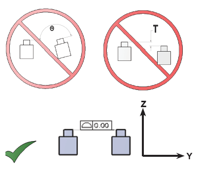
Figure 7: (Top) Parallel actuators with angle misalignment and plane height misalignment. (Bottom) Proper parallel alignment.
2. Are the actuators mounted at a consistent distance apart from each other from one end to the other?
Misalignment in this plane willapply an unfavorable side load in the fy-axis on the bearing system and if severe, may cause the units to bind. (See figure 8.)
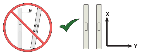
Figure 8: (Left) Angular misalignment; (Right) Proper alignment.
3. Are the actuators mounted level to each other?
Angular misalignment in the will apply an unfavorable bending moment in the My-axis on the bearing system of both units. See figure 9.)
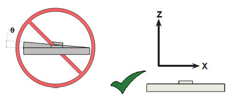
Figure 9: Angular misalignment on the left and proper alignment on the right.
Perpendicularity of joined elements
There are two variables that affect perpendicularity when mounting linear actuators.
1. In an X-Y-Z system, is the Z-axis mounted perpendicular to theY-axis?
Misalignment in this plane will apply an unfavorable bending moment on the Y-axis actuator’s bearing system in any or all possible axes. (See figure 10.)
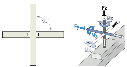
Figure 10: (Left) “Y” and “Z” actuators mounted correctly perpendicular to each other (Right) Key showing external forces on actuator
2. In a gantry system where two actuators are required to move simultaneously in the X- or Y-axis, are they moving simultaneously?
Misalignment or inadequate servo performance will apply an undesirable bending moment in the Mz-axis to the bearing system. (See figure 11.)
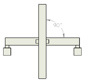
Figure 11: “Y” and “Z” actuators mounted correctly perpendicular to each othewhich must move in sync to keep “Y” actuator perpendicular to them. All actuators are mounted square and perpendicular to each other.
Actual tolerances related to alignment recommendations and mounting vary actuator manufacturer to actuator manufacturer as well as from brearing type to bearing type. However, a general rule of thumb is to consider the bearing sytem type. High performance bearing types such as profile rail systems tend to be quite rigid and alignment is more critical. Medium performance systems using rollers or wheels often have clearance which offer some forgiveness in alignment. Plain bearing or sliding systems often have greater clearance and may be even more forgiving.
When installing linear actuator mounting systems there are a number of measurement tools ranging from gauges to laser systems. Whatever tools are used, always create one axis as reference for the X-Y and Z planes and mount the other devices with respect to the reference axis. Doing so will help to get the maximum performance and longest life from your actuator system.
Conclusion
System performance and actuator life are affected in many ways when linear guidance components are introduced into the equation. Optimal system and linear actuatorperformance can be acheived if the actuaror and guidence system are carefully mounted so actuator compliance components are in place to compensate for stress points. Further, both parallelism and perpendicular alignment bending moment considerations should be addressed.

 Ask an Engineer