 Ask an Engineer
Introduction to accuracy and repeatability in linear motion systems
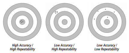
When discussing a linear motion application, many first-time or beginning users will often ask us “How accurate is this actuator?” As you will see, the answer is way more involved than simply stating a number. To fully understand the answer, we need to help the user get to a basic understanding of the actuator specifications and to what the specifications are really referring. As illustrated below, you can see that, while related, accuracy and repeatability are not the same thing. Sometimes, repeatability is more important than overall accuracy; the relative importance of the two qualities depends on a thorough understanding of your application.
First, we need to define exactly what parameters to specify. Accuracy refers to the ability of an actuator to achieve a commanded position. Said another way, accuracy is a measure of the error in commanded position vs. the actual position achieved. However, positional errors in a single-axis system can come from several sources, such as the mechanical actuator itself, the motor and its encoder and the motor driver. Each of these elements influences the accuracy and repeatability of a linear actuator system. This paper will specifically discuss the mechanical actuator platform of an example rodless actuator and how it contributes to accuracy and repeatability. Future papers will discuss related attributes of the motor and electronics of the system.
The motion control coordinate system
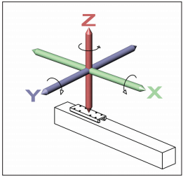
Linear actuator hardware may exhibit errors in six degrees of freedom. This is often referred to as the motion control coordinate system. As a first step, the machine designer must decide if it is important to eliminate errors in only one degree of freedom or if the goal is to accurately position the device in three-dimensional space, including all possible degrees of freedom. One way to simplify the understanding is to consider an actuator lying flat on a table. The motion errors that may occur could be in the direction of up/down (the -Z- axis), side-to-side (the -Y- axis) and end-to-end (the -X- axis). Rotation about these axes makes up the remaining three degrees of freedom for a total of six.
Six Degrees of Freedom
When you consider all the possible sources of errors and what they represent, the application parameters can seem quite confusing. To help clarify, the below applications examine the basics of an example device. When linear motion occurs, the actuator travels through its length of stroke as determined by the components and methods used in its construction. Linear actuators need to have some type of structure upon which the actuator components are mounted or attached. This may be aluminum, steel or even granite as in some very high precision devices. Some actuators are created using extruded aluminum profiles and others may utilize components machined to various degrees of precision. Attached to this structure are the driving components– such as lead screws or timing belts– along with the appropriate hardware to assure proper function. In the case of an actuator that is intended to carry or support loads such as a tooling fixture or end effector, there will also be some load-carrying components such as bearing rails and bearings. These fundamental components are the basis of the “actuator.” Now, let’s look at some possible sources of errors.
Accuracy and the linear actuator
All mechanical devices and components have dimensional and geometric tolerances associated with their manufacture. While the worst possible case—where all tolerances are at a maximum—rarely exists, it’s important to take all possible tolerances into consideration for a complete understanding of the system and evaluation of possible errors.
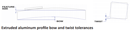
Consider a 12-inch (304.8 mm) stroke actuator that is manufactured using an extruded aluminum profile and linear ball bearing rails driven by a ball screw. Starting with the extruded aluminum profile, we know that the extruded profile will have some manufacturing tolerances. These tolerances relate to feature size as well as bow and twist.
Attached to the extruded aluminum profile are the linear bearing rails. Linear bearing systems will also have manufacturing tolerances that relate to clearances between the bearing and the rail, as well as feature size and parallelism between the base of the rail and the ball ways of the rail. Finally, the driving mechanism is the ball screw. You guessed it, the ball screw and ball nut have tolerances as well. These relate to backlash between the screw and the nut in addition to linear accuracy of the ball thread on the screw. Using this example and starting with the aluminum profile, imagine that the feature size tolerance in the motion path is +/-0.0025 inches (+/- 0.0635 mm) and all feature deviations must fit within this tolerance range. In other words, the thickness of the extruded profile is allowed to vary by +/-0.0025 inches (+/- 0.0635 mm). Using the worst case scenario, the thickness of the profile is tapered by 0.005 inches (0.127 mm) from one end to the other or, one end of the actuator is 0.005 (0.127 mm) inches taller than the other. Or, the profile may vary in its thickness or height by that same amount. As you recall from the description of the six degrees of freedom, this is referring to the -Z- axis. In addition to this feature size variation, imagine that there is also a twist tolerance of 0.005 inches (0.127 mm) per the 12 inches (304.8 mm) of stroke possible in the extruded profile. This means that one end of the extruded profile is twisted by 0.005 inches (0.127 mm) relative to the other. This is referring to rotation about the -X- axis. In addition, there is a bow tolerance which allows the extruded profile to have an overall arched shape from one end to the other up to a limit of 0.0025 inches (0.0635 mm). This comes into effect in the -Y- axis.
Next in the discussion comes mounting the linear ball bearing rail to the extruded profile. Imagine that the linear ball bearing rail assembly has some small clearance between the bearing balls and the bearing rail. It is typical for this clearance to be in the range of 0.002 inches (0.0508 mm). However, within the actuator system, it adds to the total error so it cannot be ignored.
Using the worst case scenario suggests that the bearing clearance allows possible error in -X-, -Y- and -Z- direction, so it’s a good thing this is a smaller contributor! Finally, the ball screw and nut are installed. Assume this ball screw is precision rolled with a non-pre-loaded ball nut. Backlash of this combination is 0.003 inches (0.0762 mm) and needs to be included in this evaluation of accuracy.
While backlash is perhaps easy to comprehend, how about the lead accuracy of the screw? Even a precision rolling process produces lead accuracy variations of the screw component and must also be taken into consideration when evaluating accuracy. Although there are several classes of threads produced by this process, a typical one may be ISO Class 7 which has lead accuracy of 0.002 inches (0.0508 mm) per 12 inches (304.8 mm) of travel. Therefore, with this particular ball screw, possible errors along the -X- axis due to lead accuracy could be up to 0.002 inches (0.0508 mm) along its full travel. One way to better understand lead accuracy is that even though you may have commanded the actuator to travel to 12 inches (304.8 mm), it may have only achieved 11.998 inches (304.7 mm).
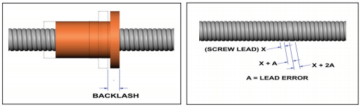
Ball Screw Backlash and Ball Screw Lead Error
Does all this potential error really matter? Sometimes it does and other times it doesn’t. It all depends on what is important in the application. With all its possible tolerances, the example actuator assembly may therefore not be a good choice when very high degrees of location precision are required. To further explain, imagine the above described actuator is installed in an application where its mounting points were only at the actuator’s end points and orientated horizontally. Tooling is then attached to the actuator carriage and extends vertically. In this application, the need for accuracy is at the end of the tooling. When linear motion occurs, it is possible for the tooling point to experience possible errors in the -Z- axis due to feature size tolerance (0.005 inches or 0.127 mm), in the -X- axis due to twist (0.005 inches or 0.127 mm) and in the -Y- axis (0.0025 inches or 0.0635 mm) due to bow. This error is magnified by the fact that the tooling is extended above the actuator carriage. In addition to this, the tooling point also exhibits possible errors due to the ball screw lead accuracy (0.002 inches or 0.0508 mm) and the ball nut backlash (0.003 inches or 0.0762 mm). Lead accuracy and backlash both effect possible errors along the -X- axis.
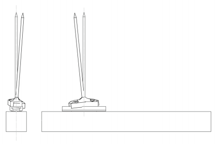
Possible Accuracy Deficiency
So in this example, the above described actuator would be a poor choice for a precision assembly application where parts needed to be placed within 0.0025 inches (0.0635 mm). The same may be true when considering multiaxis configurations where single-axis errors are compounded throughout multiple axis of motion.
Repeatability and the linear actuator
While accuracy is important in some applications cases, many applications do not require high degrees of accuracy. The point is that these tolerances exist in all actuator systems to one degree or another and must be considered when selecting an actuator. Mounting of the actuator and attention to the orientation of the loads also play a role in overall accuracy and may influence system performance.
Repeatability of the above mentioned actuator system will be a different matter. Repeatability refers to the ability to return to a predetermined position in successive attempts. Said another way, it is the error in achieving that position time after time. It is possible that a system may not have a high degree of accuracy, as the example above shows, but may in fact have a high degree of repeatability.
Consider applying the actuator described above into a different type of application. The application requirements are that the actuator is positioned in a vertical orientation, is mounted to a known flat surface, is fully constrained and there is tooling attached to the actuator carriage producing an offset load or bending moment to the linear bearing system. Imagine this application requires the tooling attached to the actuator carriage be positioned in three different defined points at 4.00 (101.6 mm), 8.00 (203.2 mm) and 11.00 inches (279.4 mm) with each position requiring +/-0.005 inches (0.127 mm) position repeatability to the required point in space.
In this application example there are several factors which will influence repeatability. For example, because this is a vertical application, ball nut backlash and linear bearing clearances have been mitigated because the gravity’s effect on the tooling/load will bias backlash and bearing clearance in the downward direction. Remember from the above example that this is referring to the actuators -X- axis. Repeatability in this axis may be considered very high, therefore, because it will relate only to long term component wear . Once the actuator is required to move to its three defined points, we can evaluate repeatability to those points. Remember that the actuator is mounted to a known flat surface. By doing so, the effects of bow and twist have been mitigated to near -0-. This only leaves the tolerance of feature size to consider. Feature size variation of this actuator is 0.005 inches (0.127 mm) along its travel length. Not only is this well within the required tolerance of the motion requirements, it is also not due to change as the actuator structure is appropriately mounted and restrained.
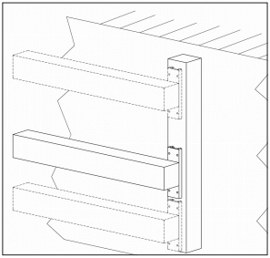
Repeatable System Application
Do you see where this is going? Accuracy, while related, is different than repeatability, particularly when attempting to achieve a pre-determined point in space. In addition, the way each actuator is deployed has significant influence on the results. While there are numerous actuator styles/types available that are manufactured to various degrees of precision and subsequent cost, this example actuator may have high repeatability and deliver excellent performance even without it being highly accurate. The key to success, therefore, is understanding what is required in your application and choosing the actuator accordingly. By doing so, you can avoid excess costs and design a system with the best overall value.