 Ask an Engineer
A technical comparison: Performance of pneumatic cylinders and electric rod actuators
Introduction
As industrial automation technology has advanced, application demands have increased for flexibility, precision, efficiency and reliability in linear motion. This has resulted in considerable debate about the best overall solution – pneumatic or electric linear motion – for automation applications.
Pneumatic cylinders have been a long-standing, popular solution for providing economical linear motion across a broad spectrum of manufacturing processes. Pneumatic systems are fairly simple to install and durable, and they provide a low-cost method of meeting linear motion and force requirements. Developments in electric rod style actuator designs and options now make electric technology an economical, viable alternative for machine builders to consider for linear motion applications. Electric actuators provide control and reliability advantages while meeting motion and force requirements.
Factors that affect performance and feasibility of each technology include:
- Motion control capabilities
- Force capabilities
- Velocity/acceleration/deceleration capabilities
- System components and footprint
- Reliability, life and maintenance of devices
- Data collection
- Efficiency/leaks/utility costs
- Shock/side loads
1. Motion control capabilities
Pneumatic cylinder systems
Standard pneumatic cylinder systems easily accomplish basic end-toend position applications. Mid-stroke positioning, however, is more complicated, requiring additional actuator and valve hardware to achieve a third position. This results in a process that is not very accurate or repeatable. Servo-pneumatic solutions exist and attempt to address this issue of positioning, but further complicate the system and add additional cost to the system. Their cost structure becomes similar to electric actuator systems. In addition to the positional accuracy and flexibility challenges of pneumatic systems, speed control can also be a challenge and require fine tuning. Speed control in a pneumatic system is monitored through flow controls; an operator must manually dial in the acceptable speed for an application, which may make an exact speed setting difficult to achieve. Once the speed setting is adjusted, the pressure force output required from a pneumatic cylinder is regulated through the valve. Again, the operator must fine-tune the system to achieve the desired force. Finally, the repeatability of position, speed and force of a pneumatic cylinder are subject to worn seals, leaks, pressure drops and spikes from the compressed air system as well as other maintenance factors. These factors often make it difficult to achieve repeatable performance shift to shift, day to day or week to week in demanding industrial production environments.
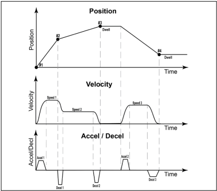
Figure 1: Motion profiles graphed at different velocities with varying accel/decel rates, all under full and precise control
Electric actuator systems
One of the main reasons engineers select an electric actuator system over a pneumatic cylinder system is to increase the flexibility and motion control capabilities in their machines and processes. This includes position control (multiple positions, accuracy, repeatability); velocity control; control of acceleration/deceleration; control of output force; and complex control of all these motion variables at any time during the motion. Electric actuators, coupled with a servo drive and motor system, offer infinite control over position, as well as increased position accuracy and repeatability, far beyond the capabilities of current pneumatic systems. Additionally, multiple-axis servo controllers are readily available off the shelf for most modern control systems today and can be easily integrated with multiple linear and rotary axes to create complete motion solutions capable of running even the most complex motion profiles. This improved motion control and flexibility is programmable into PLCs, HMIs and other controllers. Machine start-up change-over times are fast and repeatable. With this improved capability, OEMs are able to easily optimize system performance, helping end-user manufacturers improve their overall process.
2. Force capabilities
Pneumatic cylinder systems
Pneumatic systems typically operate on pressures from 80 to 100 psi or 5.5 Bar to 7 Bar. Since pneumatic cylinders operate on the Force = Pressure x Area fluid power principle, the forces achievable are easily calculated for a pneumatic cylinder. For example, 1-inch and 3-inch bore cylinders at 80 psi could achieve approximately 63 lbf (0.28 kN) and 565 lbf (2.51 kN), respectively. However, pneumatic cylinders are typically not used to their full output force capability and are often oversized to improve control to ensure system operation. In pneumatic systems, where system rigidity is not optimized, the pneumatic cylinder may experience a delay in force generation due to the lag in time while system pressure is built up to complete the work. This phenomenon often makes it difficult for a pneumatic system to repeatedly produce the same force for each cycle in a repeating process.
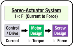
Figure 2: Electric actuator systems precisely regulate current through the servo motor to achieve accurate and repeatable force.
Electric actuator systems
Servo electric actuator systems precisely control current through the servo motor to produce torque to the mechanical system, which drives the screw assembly to rotate resulting in linear movement and force. This is a significant advantage as force generation is almost instantaneous and essentially “on demand.” Another advantage of electric systems is the servo controller’s precise closed-loop control of the current, which creates precise and repeatable force performance. This allows force limits to be programmed to achieve consistent force for each cycle or to prevent damage to the product or system in which the actuator is integrated.
Electric actuators typically can achieve much higher forces than pneumatic cylinders due to the large variety of servo motor offerings (RPM and torque capabilities) combined with many screw lead and gearing ratios. Finally, when selecting an electric actuator system, it is important to consider the motor’s RPM and torque capabilities, coupled with the screw lead in the electric actuator. Carefully match the servo motor RPM and torque with the actuator’s screw lead and gearing. Although this step may appear to complicate the process, many actuator and servo component manufacturers provide easy-to-use sizing software packages that take all these variables into consideration.
3. Velocity, acceleration and deceleration capabilities
Pneumatic cylinder systems
Pneumatic cylinders can achieve very high velocities if compressed air volume and pressure are readily available. When sufficient volume and flow are available, pneumatic cylinders operate at high cycle rates in basic end-to-end positioning applications without the need for detailed sizing or thermal analysis. A common challenge of pneumatic systems is that the velocity of commanded motion is difficult to control accurately and repeatedly, and engineers must factor acceleration/deceleration rates into their machine designs. Machine designers operating a pneumatic cylinder at high linear speeds or with high acceleration and deceleration rates must typically either consider shock absorbers or make additional design considerations to plan for the shocks and impacts that may be present. If not factored into the machine design, these shocks and impacts can negatively affect the life of the cylinder and components in the machine design.
Electric actuator systems
Electric actuator systems can precisely and accurately control velocity and the acceleration/deceleration profiles throughout the motion profile, easily blending from one speed to another without stopping or over-running position. This capability creates opportunities for machine designers to further optimize machine performance and also helps minimize move times, decreases cycle time and increases overall machine productivity. Further improvements come with smooth motion throughout the motion cycle, eliminating the potential for shocks and impacts into the machine structure, which improves the overall reliability of the machine design.
As with achieving high force, achieving high speed at force also presents a more involved sizing process with the combination of screw leads, gearing and the servo motor RPM/torque possibilities. The combined limitations of the screw lead, gearing and servo motor may limit the maximum achievable velocity of the electric actuator system. In some cases, pneumatic systems may achieve higher overall linear velocities. However, overall motion cycle time can often be decreased when utilizing an electric actuator operating at similar, but lower, velocities.
4. System components and footprint
Pneumatic cylinder systems
A system’s total component count is an ever-important consideration for engineers. Pneumatic systems require a cylinder; a compressor or compressed air system; valves; filters; regulators; tubing; fittings; as well as additional ancillary components. This results in an increased component count compared to an electric motion system. Pneumatic cylinders offer a compact footprint at the work point (where the power density is required), but require a compressor or a compressed air system, which takes up additional floor space at the machine, or require a compressor room, which consumes significant plant floor space. Factoring the compressor into the overall system footprint, the pneumatic solution would have an overall larger footprint on plant floor space. Additionally, most compressed air systems require overhead air hoses and air drop lines to bring the compressed air to the work station. These long lengths of air hose create additional volume of air to compress, increase the potential leakage points and decrease overall system efficiency.
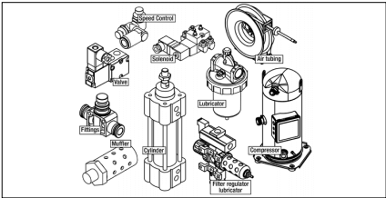
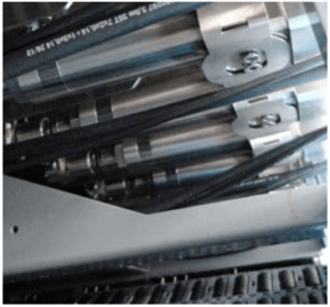
Figure 3: Pneumatic system components
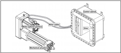
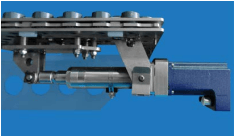
Figure 4: Electric actuator system components
Electric actuator systems
Electric rod actuators are physically larger than their pneumatic cylinder counterparts and are almost never drop-in replacements. They typically require additional space to accommodate increased length and width compared to a pneumatic cylinder. However, electric actuator systems utilize fewer components: a mechanical actuator; a motor (servo, or other); an optional gearbox; cables; and a drive/amplifier, which is usually mounted in a control cabinet. Although the electric actuator — due to its integrated ball or roller screw assembly and bearing system — does require additional length over a pneumatic cylinder. When considering the overall system footprint, this additional length is more than compensated for by the much smaller footprint of the servo drive — the functional equivalent of the compressor. Size requirements for a servo drive are normally a fraction of the size requirements of a compressed air system with multiple compressors.
5. Reliability, service life and maintenance
Pneumatic cylinder systems
With proper maintenance and installation, pneumatic cylinders can offer rugged performance and provide a long service life. The key to achieving long service life is the integrity of the rod and piston seals. These sealing elements must achieve and maintain proper tolerances to contain the pressure required for motion and force. As the cylinder cycles back and forth, seal wear is inevitable. Efficiency, force output, speed and/ or responsiveness of the cylinder decrease as air leakage increases. Not only will the performance degrade, but the seal and/or the cylinder itself will require replacement. All of these factors reduce the probability of achieving consistent manufacturing processes required for high-quality, high-volume production.
Predicting when the seals may fail, or anticipating the effect on cylinder performance to ensure proper and timely maintenance, can be almost impossible. As seals wear, operators must spend time manually adjusting the air flow rates and pressures on individual devices to ensure proper operation of the machine and process repeatability. Additional labor hours are required when cylinders must be replaced or refurbished. Not only are these activities time-consuming, but variation between operations is common, further complicating the goal of achieving repeatable manufacturing processes. Many manufacturing facilities have developed dedicated preventative maintenance and replacement schedules for their pneumatic cylinder machines to avoid unexpected downtime. In doing so, they must also schedule additional time to test and tune systems on startup. While pneumatic cylinder periodic maintenance plans offer increased machine and process reliability, they introduce additional costs in time, labor, replacement parts and managing the preventive maintenance schedule.
A final factor to reliability and service life with pneumatic cylinders and compressed air systems is maintaining a clean/dry air supply that is free of moisture. Condensation in air lines can cause premature failure of pneumatic components through corrosion as well as create an environment risk through bacterial growth, which can contaminate the manufacturing process.
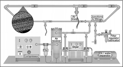
Figure 5: Pneumatic/compressed air systems require increased maintenance due to the extensive system structure.
Electric actuator systems
Electric actuators systems can be sized for the life requirements of an application. The main torque and force transmission elements of an electric actuator are the screw assembly (ball or roller screw) and ball-bearings. These components have a Dynamic Load Rating (DLR) specification that estimates the service life an electric actuator can achieve. Utilizing an industry standard L10 life estimation, electric actuators can be sized and selected to meet the machine life requirements. (See our guide “Actuator Life: How to estimate for ball and roller screw actuators”.) These force/torque transmission elements are typically greased for life, but, easy in-field greasing methods are available for demanding applications to extend service life.
A secondary wear element on an electric rod-style actuator is the rod seal, designed to keep water, dust and other environment contamination from entering the actuator and damaging the internal torque transmission components. Unlike pneumatic cylinder seals, the seals in electric actuators are not subjected to the precise sealing requirements necessary to contain high pressures needed for motion. Even if the seal fails, the actuator will continue to operate. Rod seals on most electric actuators can be easily and inexpensively replaced. Misuse is the primary reason that electric actuators fail. For example, exceeding the actuator’s performance specifications for extended periods of time and damage during commissioning or installation due to inadequate attention to controls parameters are the most common misuse factors.
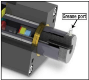
Figure 6: This electric actuator has a unique, easy-to-use re-lubrication port feature to maximize operating life.
6. Data collection
Pneumatic cylinder systems
In the never-ending quest to improve manufacturing processes and improve process control, data collection in critical areas of the manufacturing process has become common in today’s manufacturing environment. Pneumatic cylinders may have proximity sensors with IO Link or an Ethernet valve bank, but without expensive linear transducers and other sensors to provide absolute positioning feedback, the information reported back to the controls system is often inadequate to tightly monitor and control a process in real time.
Electric actuator systems
The fundamental design of electric actuator systems allows for increased in-process data collection. In the electric motion system, the servo drive regulates current and voltage to the motor. Most servo drives are offered off the shelf with features allowing users to monitor and export current and voltage parameters to data acquisition systems. The current supplied to the motor can be easily used to track force and repeatability. The feedback device on the motor registers accurate position, velocity and acceleration/ deceleration during the entire motion cycle at any point in time. The availability of this data for every cycle allows engineers to closely monitor the actuator’s operation and improve machine performance, reliability and process control.
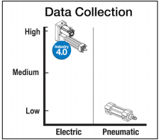
Figure 7: Enhanced data collection capabilities of electric systems through Ethernet connectivity enable Industry 4.0 and Internet-of-Things (IoT) machine designs.
7. Efficiency, leaks and electric utility costs
Pneumatic cylinder systems
Pneumatic cylinders, the support components, and the compressed air system typically operate in the 10-20 percent efficiency range. Many factors can affect the efficiency of the entire system over time, including the number of components, leaks and quality of air. As efficiency changes, so can accurate and repeatable performance. Additionally, pneumatic systems must stay pressurized at all times to ensure specified motion and force. When the system is active, the compressors must be running even though many of the cylinders may not be in operation, resulting in an inefficient use of power. This issue is further magnified if leaks are present in the compressed air system. The compressor will continue working, providing air pressure and volume flow to the system, while the air continues to escape through the leaks. Even an accumulation of several small leaks can result in significant air loss. Increased demand from the compressor unit adds to electric utility costs. In large plants with complex compressed air systems, it can often be very difficult to locate and fix all of the leak points in a system.
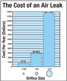
Figure 8: Cumulative air leaks in a compressed air system across an entire facility can be very costly. Costs calculated using the industrial electricity rate of $0.07 per kWh,* assuming a consistent operation and an efficient compressor.
*From U.S. Energy Information Administration, December 2012 Electricity Consumption Report
Electric actuator systems
Electric actuator systems typically operate in the 75-80 percent efficiency range (five to eight times higher than pneumatic/compressed air systems) during their operation. Due to the mechanical construction and torque transmission components, this efficiency remains very consistent over time. An additional factor in the electric utility cost equation is that electric actuators only demand current to the motor when the force (torque) is required for their operation. This means that when electric actuators are at rest, they require little to no current to hold their positions (unless force is required). While a pneumatic system always requires energy input into the system to maintain system readiness and responsiveness, an electric system allows for motion on demand and achieves a high efficiency range when operation is required. The use of holding brakes can further increase application efficiency, while holding large loads in place and allowing power to the actuator to be switched off.
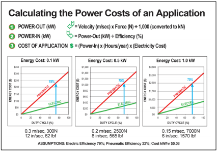
Figure 9: Method to calculate power usage and estimate electric utility costs. Blue arrows depict cylinder operation at 75 percent duty cycle.
With increased regulation requiring many manufacturing companies to limit or cap their electric utility usage, in turn limiting compressed air usage, electric actuator technologies are often utilized to decrease electric utility usage and meet green and energy efficient initiatives.
8. Shock and side loads
Shock loads
Pneumatic cylinders, with their construction containing a volume of compressed air, provide an inherent air cushion and increased ability to withstand shock loads. A shock load in line with the rod would be absorbed in most cases by the piston against the compressed air in the body of the pneumatic cylinder.
Electric actuators, with their screw assembly and bearing system, must consider shock loads with respect to the actuator life. Depending on shock load size and actuator construction, some applications may require the electric actuator to be oversized in order to handle shock loads. The use of a roller screw, with its increased contact points, can further increase shock load capabilities of an actuator. Furthermore, depending on the size of shock load either a shock absorber should be utilized or the design should be reevaluated as it could significantly diminish the overall service life of the actuator.
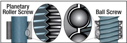
Figure 10: Roller screws increase shock load capabilities of an electric actuator.
Side loads
Side loading — due to misalignment or pressure from a moment arm — places stress on both pneumatic cylinder and electric actuator systems. When mounting either technology, the cylinder must be aligned in the system with the intended axis of motion.
A side load on the rod and piston seals of a pneumatic cylinder will cause premature wear or failure of the seals, resulting in poor performance with velocity and force, increased leaks and premature failure of the cylinder.
Electric actuators don’t perform well in side load scenarios either, but for different reasons. Side loading results in lateral forces on the actuator’s front rod seal as well as the screw/nut assembly. Increased loading on the rod seal can often result in increased wear, allowing contaminants into the actuator and causing premature failure of the screw and bearing assemblies. Additionally, side loading the screw/nut assembly can reduce the estimated life of the ball or roller screw. However, unlike pneumatic cylinders, electric actuators typically contain an anti-rotate mechanism. This anti-rotation feature adds additional screw support as it rides on the inside of the body tube, which allows it to absorb some side-loading.
Summary
Pneumatic cylinder systems
Pneumatic cylinders have a long-standing industry reputation as economical automation components. A pneumatic cylinder axis of motion (assuming a compressed air system is already in place) is significantly less expensive, from a purchased component cost standpoint, to implement than an electric actuator/servo system. Although this technology offers an initial low investment cost, pneumatic cylinders have many drawbacks when compared to electric actuator systems, including limited motion control flexibility (typically two position), an increased component count to install and maintain, shorter and unpredictable life, increased maintenance and replacement costs, manual system adjustments and significantly higher electric utility costs.
Electric actuator systems
Electric systems provide complete motion flexibility combined with improved position, velocity, acceleration/deceleration and force control for allowing engineers to achieve more repeatable and reliable machine designs. With this flexibility, electric actuators can be correctly sized for the life of the application, offering a robust motion solution. Additionally, electric actuators operate with closed loop control providing easy data collection and improved process control. These systems are virtually maintenance free and operate at very high efficiencies, which lowers the overall electric utility cost and eliminates the need for expensive compressed air systems. Analyzing all of the attributes of an electric actuator system in detail, electric actuators are often found to offer users a lower total cost of ownership versus alternative pneumatic systems over the life of the system, even though the initial purchase price of an electric system can be several times higher.
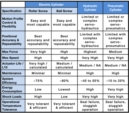
Figure 11: Summary of application specifications impacting performance and selection for electric, hydraulic, and pneumatic cylinders.