 Kontakt zu einem Ingenieur
Understanding Servo Linear Actuator Systems
John Fenske
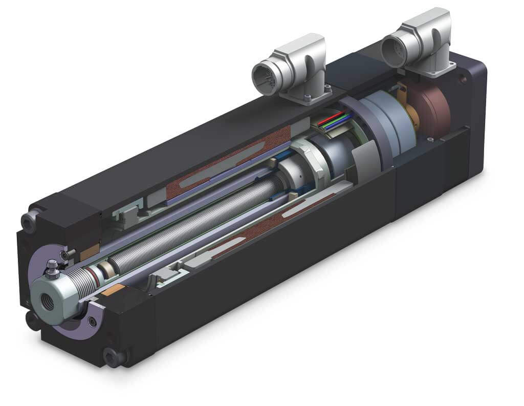
Today’s automation industry increasingly relies on high-performance electric actuators, especially integrated actuators, because of their dynamic responsiveness and precision capabilities. When assessing actuator performance for designs, engineers often rely on continuous force/speed curves derived from motor performance. But these curves don’t completely represent the intricacies of the integrated linear actuator’s performance. Integrated actuators have a number of unique attributes that contribute to the overall performance of the entire linear motion system.
Because they don’t depict the overall actuator performance, over-reliance on continuous force/speed curves can lead engineers to under-size actuators for their designs, resulting in system performance issues and costly delays. Although continuous force/speed curves enable high-level estimations, they don’t account for all losses inherent to a complete integrated actuator system.
To specify an integrated actuator and ensure its performance meets expectations, engineers should consider all mechanical and thermal limitations of the actuator system. Not only does this complete approach save time and money by avoiding under-performing systems, it also maximizes actuator usability. The first step is to evaluate integrated actuator performance within the context of full system operation by looking beyond continuous force/speed curves.
Limitations of Standard Motor-Based Performance Curves
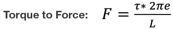
The continuous force/speed curves for most integrated actuators are generated by simply converting the values of the servo motor’s standard continuous rotational torque/RPM curve into linear units using the screw’s lead and efficiency values. The following equations are used:
Where:
- τ is the input torque to screw from the motor (Nm)
- F is the output force (N)
- L is the screw lead (mm/rev)
- e is the screw efficiency (~90% for ball screws, ~70% for roller screws)
![]()
Where:
- VL is the linear velocity (mm/s)
- VR is the rotational velocity (rpm)
Using the above equations results in a curve that only considers the motor’s operating limits in a purely continuous rotational system. However, this curve doesn’t account for linear movement back and forth, acceleration, deceleration, additional heat generated by the screw, the screw’s thermal limitations and other limitations that can prevent severe life degradation.
This curve represents the integrated actuator’s theoretical performance according to the motor’s information, but it can be improved with additional system parameters and limitations. Accounting for these parameters produces different curves which, depending on the parameters used, provide greater understanding of the integrated actuators’ capability.
Developing Better Performance Curves
To represent performance with greater accuracy, first introduce the losses attributed to real-world operating conditions with mechanical limitations. Include losses such as those from system acceleration and deceleration during back and forth movement, the frequency of which is determined by the stroke. While including these losses lowers the upper limit of performance, it provides a more realistic expectation of an integrated actuator.
|
Category |
Parameter |
Standard |
Physically Limited |
Thermally Limited |
|
Motor |
Raw Motor Data |
Yes |
Yes |
Yes |
|
Mechanical |
Screw Lead |
Yes |
Yes |
Yes |
|
Screw Efficiency |
Yes |
Yes |
Yes |
|
|
Back and Forth Motion |
No |
Yes |
Yes |
|
|
Acceleration |
No |
Yes |
Yes |
|
|
L10 Implications |
No |
No |
Yes |
|
|
Thermal |
Screw Heat Generation |
No |
No |
Yes |
|
Motor Heat Generation |
Yes |
Yes |
Yes |
|
|
System Heat Generation |
No |
No |
Yes |
|
|
Motor Losses |
Yes |
Yes |
Yes |
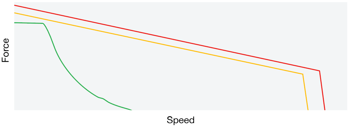
A comparison between standard (red), physically limited (orange) and thermally limited (green) force/speed curves.
Next, add parameters for the screw that drives the linear motion. Screws are not 100% efficient — they generate heat as they move and contribute to the system’s total heat generation. Losses due to the motor’s stator windings, magnetic core and mechanical components also generate heat. Because screws have a lower thermal threshold than the motor, the screw lowers the system’s thermal limit overall.
Operating the integrated actuator within this lower thermal limit protects the screw and ensures its estimated L10 life does not decrease. Because roller screws have a lower efficiency and thermal limit compared to ball screws, these limitations can be quite significant. These additional parameters provide the most accurate visual representations of the system’s performance because the resulting curves are thermally limited.
When the integrated actuator’s critical parameters are applied, the force/speed performance curve offers an excellent representation of general system-level limitations. But keep in mind that the curve is just a visual representation — it cannot be used to compare all real-life performance cases.
For even deeper insight into integrated actuator performance in a particular application, pair the performance curve with an actuator sizing software that uses all the underlying equations for generating the curves.
Sizing Up an Actuator
Sizing software analyzes an application’s specific motion profiles and provides suitable solutions by calculating application requirements and comparing them to specific pass/fail criteria. Similar to performance curves, sizing software is manufacturer-dependent — the criteria which determine pass/fail results can differ. Understanding the underlying criteria is crucial to effective use.
Several manufacturers offer proprietary sizing software for their actuators. In contrast, ServoSoft is a manufacturer-neutral option that features a wide variety of supplier products. ServoSoft features mechanical, thermal and motor pass/fail criteria including:
- Maximum stroke, force and velocity
- Motor voltage
- Continuous and peak torque
- Peak and RMS rpm
- Motor thermal limitations
Tolomatic’s online sizing software — SizeIt — offers even more criteria including:
- Acceleration limitation
- Buckling load
- Critical speed
- Screw thermal limitation
- System thermal limit
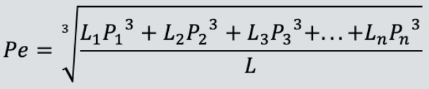
What is the L10 of Electric Linear ActuatorsL10 is the calculated lifespan after which it is expected that 10% of the bearings will fail due to fatigue according to the actuator and application characteristics. Determining the lifespan of a ball or roller screw linear actuator is simple with an L10 life formula, which focuses on the bearing components of the driving screw/nut assembly. The formula considers key actuator parameters such as dynamic load rating (DLR), which is often provided by the manufacturer and represented as C. The DLR is the constant load that a ball bearing can withstand and achieve 1 million revolutions of rated life. Understanding whether the actuator undergoes constant or varying loads during the working cycle is also important. Constant loads are straightforward because it’s the actual load used in the calculation. But varying loads require the equivalent dynamic load (Pe) which represents a load that, if applied constantly, would have the same effect as the combined actual loads. Here is the constant-load formula for calculating L10:
Where:
The formula is identical for a variable load, but the Pe must be calculated to accommodate each different load throughout the working cycle. Use this formula:
Where:
|
Expert Design Calls for Expert Resources
The performance data provided by manufacturers makes it possible for engineers to estimate a linear system’s performance in an application. But depending on what considerations the manufacturer includes, it may be necessary to dig a little deeper into system limitations. A thorough consideration of the potential losses provides a more accurate assessment of the actuator’s real-world performance, anticipated service life, maintenance schedule and failure risks.
It is best to first gather all of the information relevant to your motion profile and enter it into a comprehensive sizing software. This provides a surefire method for engineers to thoroughly understand the complexities and capabilities of their integrated actuator.
Working with your manufacturer and explicitly defining your system requirements early in the process allows the manufacturer to deliver the most accurate data. This will help you balance the cost and performance of the finished design.
Check out our online engineering tools or ask an engineer to learn more.